Non-spinning connector housing – MTS SWIFT 30 Sensor User Manual
Page 20
SWIFT 30 Sensors
20
Construction
Hardware Overview
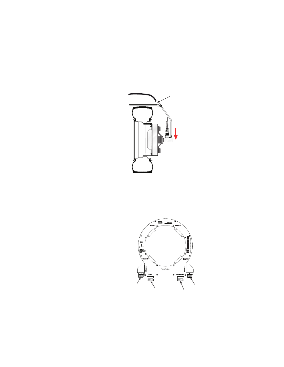
The anti-rotate device should be configured such that no loading occurs to the
slip ring throughout all loading and suspension travel. This means that when you
attach the anti-rotate device to the vehicle, you must consider all possible motion
of the suspension. The anti-rotate device should not bump against the wheel well
at any time; any jarring of the anti-rotate arm will damage the slip ring. For
steering axles, the anti-rotate bracket must be mounted to part of the unsprung
suspension that steers with the tire, such as the brake caliper. For additional anti-
rotate device mounting recommendations, refer to the Anti-Rotate Customer/
User Assembly drawing at the back of this manual.
Non-spinning
connector housing
The non-spinning connector housing or the non-spinning connector bracket (both
shown below) provide a connection between the SWIFT and the TI electronics
for non-spinning use. Both assemblies incorporate rugged connectors suitable for
durability testing. The non-spinning connector housing can also include an
optional connector with built-in, tri-axial accelerometers.
Wheel Well
A jarring motion
will damage the
slip ring
Allow enough clearance
for all loading and
suspension travel
S20-05
Shunt B
Shunt A
Accelerometer
(optional)
Load
S30-25
Connector Housing