Lenze SCD Series User Manual
Page 25
22
11.5
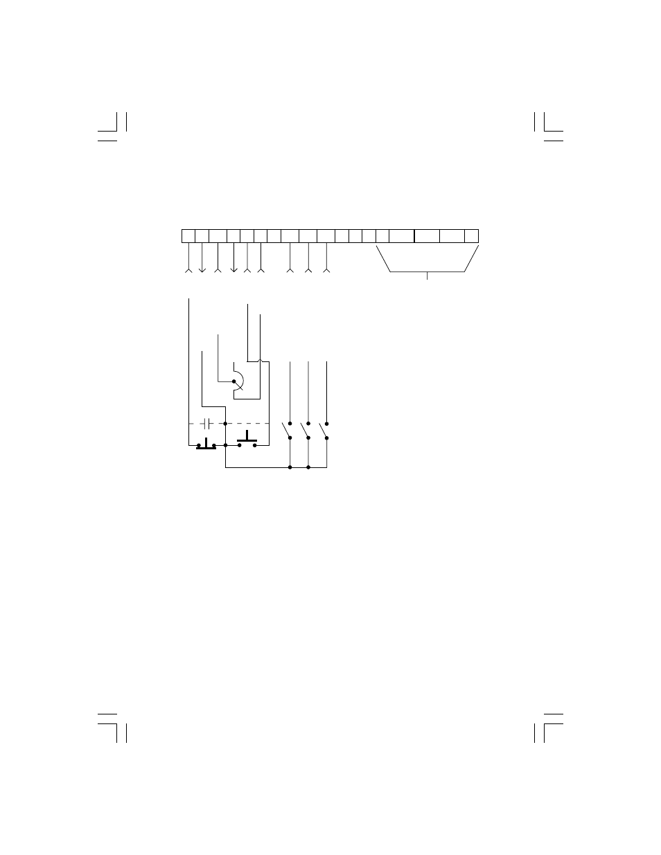
SPEED POT AND PRESET SPEED CONTROL
Shown below is the wiring for SPEED POT and/or PRESET SPEED control, and either a two-wire or
three-wire start/stop circuit:
NOTES:
1.
Program the PRESET SPEEDS (Parameters 31-37) to the desired values.
2.
Program TB-13A (Parameter 10) to PRESET SPEED #1 (04), TB-13B (Parameter 11) to PRESET
SPEED #2 (04), and TB-13C (Parameter 12) to PRESET SPEED #3 (04). To select a preset
speed, close the appropriate TB-13 terminal(s) to TB-2 (refer to Parameters 31-37 for the Preset
Speed Activation table).
3.
If reverse rotation is also required, TB-13A cannot be used as a PRESET SPEED SELECT. TB-
13A must be programmed to select RUN REVERSE (05) or START REVERSE (06), leaving
only TB-13B and TB-13C to select preset speeds.
4.
For speed pot control, program Parameter 05 - STANDARD SPEED SOURCE for 0-10 VDC
(03). If none of the preset speeds are selected (all of the TB-13 terminals are open), the drive will
respond to the speed pot.
STOP
START
STOP
DIGITAL INPUT REF.
0-10 VDC INPUT
START
COMMON
PRESET SPEED SELECT
1
4 5/25 11
2
CAN+ V+
14
13B 13C 15
13A
30
V-
12
31
SHLD
CAN-
12 VDC POWER SUPPLY
PRESET SPEED SELECT
PRESET SPEED SELECT
DEVICENET
TM
INTERFACE
Removable Connector
(Refer to Appendix B)