Lenze SCD Series User Manual
Page 20
17
MOTOR OPERATED POT (MOP) / FLOATING POINT CONTROL
TB-13B and TB-13C are used for this function, which controls the drive speed using contacts wired
to the terminal strip. Program TB-13B for DECREASE FREQ (05), and program TB-13C for
INCREASE FREQ (05). Closing TB-13B to TB-4 will cause the speed setpoint to decrease until the
contact is opened. Closing TB-13C to TB-4 will cause the speed setpoint to increase until the contact
is opened. The INCREASE FREQ function will only operate while the drive is running.
NOTE: If TB-13A, TB-13B, and TB-13C are all programmed to select speed references, and two or
three of the terminals are closed to TB-4, the higher terminal has priority and will override the others.
For example, if TB-13A is programmed to select 0-10VDC, and TB-13C is programmed to select
PRESET SPEED #3, closing both terminals to TB-4 will cause the drive to respond to PRESET
SPEED #3, because TB-13C overrides TB-13A.
The exception to this is the MOP function, which requires the use of TB-13B and TB-13C. This
leaves TB-13A to be used for some other function. If TB-13A is programmed for a speed reference,
and TB-13A is closed to TB-4, TB-13A will override the MOP function.
10.7
ANALOG OUTPUT SIGNALS
Terminal TB-30 can provide a 0-10 VDC or a 2-10 VDC signal proportional to output frequency or
load, and TB-31 can provide the same signals proportional to load only. The 2-10 VDC signal can be
converted to a 4-20 mA signal using a resistor in series with the signal such that the total load
resistance is 500 Ohms. Refer to Parameters 08 and 09 in Section 15.0 - DESCRIPTION OF
PARAMETERS.
NOTE: These analog output signals cannot be used with “loop-powered” devices that derive power
from a 4-20 mA signal.
10.8
DRIVE STATUS DIGITAL OUTPUTS
There are two open-collector outputs at terminals TB-14 and TB-15. The open-collector circuits are
current-sinking types rated at 30 VDC and 50 mA maximum.
The open-collector outputs can be programmed to indicate one of various drive status conditions.
Refer to Parameters 06 and 13 in Section 15.0 - DESCRIPTION OF PARAMETERS.
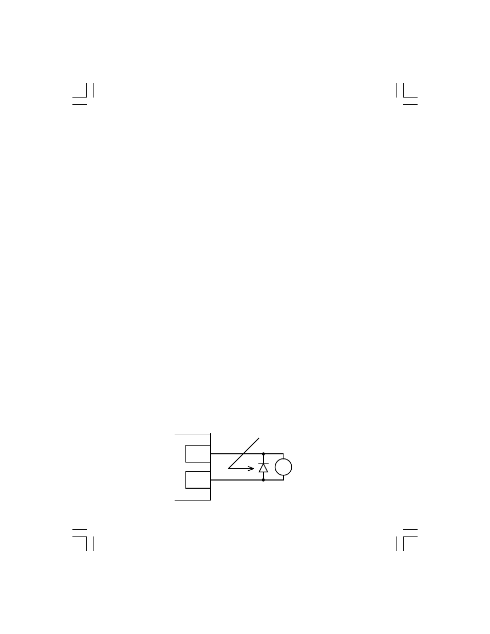
The diagram below illustrates how the 12 VDC power supply at TB-11 can be used with the open-
collector output to drive an external relay:
TB-11
TB-14
SCD TERMINAL
STRIP
RELAY COIL
DIODE SNUBBER
(1N4148 or Equivalent)