ETC SineWave Power Module (DMX) User Manual
Page 7
IES PowerModule Operators’ Manual v1.4 Isine
7
relates to the number of dimmers in the
PowerModule – either 2, 4 or 6.
Note: A questionmark (?) adjacent to the DMX
address shows the DMX signal is not
valid, and the ‘v’ adjacent to the DimSTAT
address number indicates communication
is active.
6.4 General controls
PowerModule dimmers have the capacity to store
performance characteristics individually for each
dimmer or combined for all dimmers in the module.
This feature is independent of the choice of DMX
numbering scheme, thus the dimmers may have
individual characteristics, but with consecutive DMX
addresses.
6.4.1 To change the dimmer characteristic set-up
scheme:
1. Press INST.
2. Press Ð or Ï to choose GENERAL
SETTINGS menu.
Press ENT.
3. Press Ð or Ï to choose CONFIG
CHANNEL menu.
Press ENT.
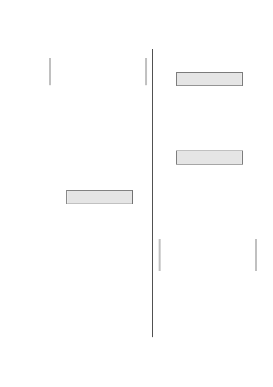
4. The screen shows:
GENERAL
CH_CONF. [SINGLE]
5. Use Ï or Ð to select either SINGLE (for
different individual channel parameters) or
JOINED (if all dimmers have the same
characteristics).
6. Press ENT (to record the changes) or
EXIT (to leave the previous settings
unchanged, and return to the home page).
6.5 DMX programming
Each dimmer in the PowerModule is assigned a
DMX channel number. A feature is provided to set
sequential number groups (‘Start’ addressing)
instead of individual settings. When programming a
PowerModule, IT IS IMPORTANT TO SET THE
DMX ADDRESSING SCHEME before the individual
characteristics are set, as a later change can reset
previously recorded individual channel characteristic
settings.
6.5.1 To set up DMX addressing scheme:
1. Press INST.
2. Press Ð or Ï to choose GENERAL
SETTINGS menu.
Press ENT.
3. Press Ð or Ï to choose DMX ADDRESS
menu.
Press ENT.
4. The screen shows:
GENERAL
DMX MODE [SINGLE]
5. Use Ï or Ð to select either SINGLE (for
different individual DMX addresses) or
JOINED (if the dimmers are numbered
sequentially from the start address).
6. Press ENT (to record the changes) or
EXIT (to leave the previous settings
unchanged, and return to the home page).
6.5.2 To set-up DMX addresses:
1. First set the DMX scheme as described
above (either individual or start address).
2. Press DMX, and the screen displays:
DMX: [001]
002
CHAN.: 1
2
3. If SINGLE has been selected, two
channels are displayed at a time, with their
relevant DMX address. Use Ï and Ð to
select the address needed for the first
dimmer channel and move to other
channels by pressing Í and Î and
continue adjusting each DMX address by
pressing Ï and Ð as before.
4. If JOINED has been selected, only one
DMX number line is entered which is the
number for dimmer 1. The remaining
dimmers are automatically addressed in
sequential order. Press ENT to store the
settings and to return to the previous
menu.
Note: DMX address 000 deselects the channel
from operation. Valid DMX numbers are
between 001 - 512. If higher dimmer
numbers are used by the control desk, the
number has to be rationalised to a base of
512 for the dimmer address.
6.5.3 To set up a DMX backup condition
The PowerModule is equipped with a choice of
responses to the failure of the DMX signal. The
dimmers can be set to hold their last DMX level,
fade to zero over 5 seconds, or fade to a preset
memory setting. This choice is available per
PowerModule.
1. Press INST.
2. Press Ð or Ï to choose GENERAL
SETTINGS menu. Press ENT.