Rough-in line conduit to the auxiliary enclosure – ETC Unison Auxiliary Enclosure Series User Manual
Page 15
3
Rough-in Conduit and Wiring
12
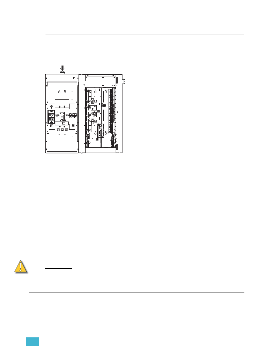
Rough-in Line Conduit to the Auxiliary Enclosure
Line input wires in main lug, main breaker, or cross-bussed DRd enclosure applications
terminate first in the Auxiliary enclosure and then are fed through the side conduit
knockouts to the adjoining DRd enclosure(s).
The line feed-through (interconnect) cables for phase, neutral and ground lugs in the
auxiliary enclosure are connected for you at the factory. Your enclosure is supplied with one
or two sets of interconnect cables depending on the model ordered.
Step 1:
Plan wire entry in to the enclosure.
See “Wire Routing and Specification” on
Step 2:
Remove the side conduit knockout from adjoining side of the auxiliary enclosure
and the DRd enclosure. When installing in a cross-bussed application, remove
both side knockouts.
Step 3:
Install the ETC supplied nylon insulated chase nipple to the knockouts between
the auxiliary and DRd enclosure(s).
Step 4:
Remove the auxiliary enclosure front cover, and if necessary, the top or bottom
front trim covers for complete access to the lugs.
Step 5:
Punch conduit holes, top or bottom, as required by the wire entry plan.
Step 6:
Install conduit fittings or insert fish paper lining material into the opening.
Step 7:
Be sure there are minimal air gaps.
See “Sealing Enclosure Air Leaks” on
C A U T I O N :
Wire openings must have fittings, grommets or fish paper lining material to protect
wire and cable insulation from damage by sharp metal edges and to prevent air
leaks.
When using the 400A breaker frame you must replace the plastic lug covers for
compliance and safe operation.
Line input may enter the auxiliary enclosure from
the top or bottom.
The ETC supplied line feed interconnect cables
will feed through the side conduit knockouts to the
adjacent DRd. Reference
Interconnect Cables to Adjacent DRd
for interconnect cable
termination instructions.