Install enclosures, Mounting auxiliary and drd enclosures together, N o t e – ETC Unison Auxiliary Enclosure Series User Manual
Page 12
9
Unison Enclosure Installation
C h a p t e r 2
Install Enclosures
Mounting Auxiliary and DRd Enclosures Together
One DRd may be bussed to the AX series auxiliary enclosure, which contains a main circuit
breaker (MCB) for power distribution to the adjacent DRd enclosure.
Two DRd12 enclosures may be cross-bussed to an AX12X which is designed to provide
main lug or main breaker input feed termination to the adjacent DRd12 enclosures.
The wall must be strong enough to hold all enclosures fully populated with modules, conduit
and wire. Reference
“Where to Install the Enclosure,” page 6
clearance requirements.
Step 1:
Determine where your enclosures will be installed using the weight and
dimension requirements detailed in
“Where to Install the Enclosure,” page 6
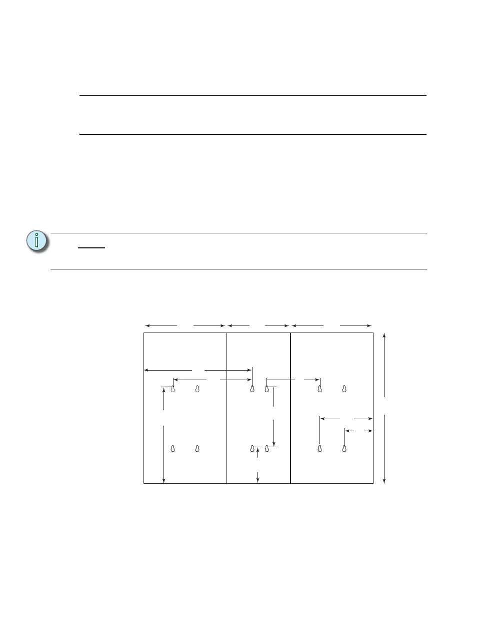
Step 2:
Use the measured slot dimensions located in the graphic below to mark the hole
locations for the mounting hardware.
Step 3:
Drill the holes and install the mounting hardware for each enclosure.
• Four 3/8” (8mm) bolts or screws 2 to 4" (50-100mm) long, and suitable wall
plugs are suggested mounting hardware (lag bolts recommended).
• Both the surface and the mounting hardware must support the weight of
the enclosure unit fully populated with modules.
• Expose at least 1" (25mm) of threads for mounting.
N o t e :
The AX series enclosure is best installed to the left of the DRd in main lug and
main breaker applications and must be installed between two DRd12 enclosures
in a cross-bussed application.
AX6 / DR6 - 16.3”
AX12 / DR12 - 19.9”
16”
11”
AX6 / DR6 - 5.7”
AX12 / DR12 - 7.7”
22”
AX6 / DR6 - 21.9”
AX12 / DR12 - 31”
10.7”
6.3”
AX6 / DR6 - 10.6”
AX12 / DR12 - 7.7”
17”
17”
13”
DRd
DRd
AX