Enerpac E-Series User Manual
Page 3
3
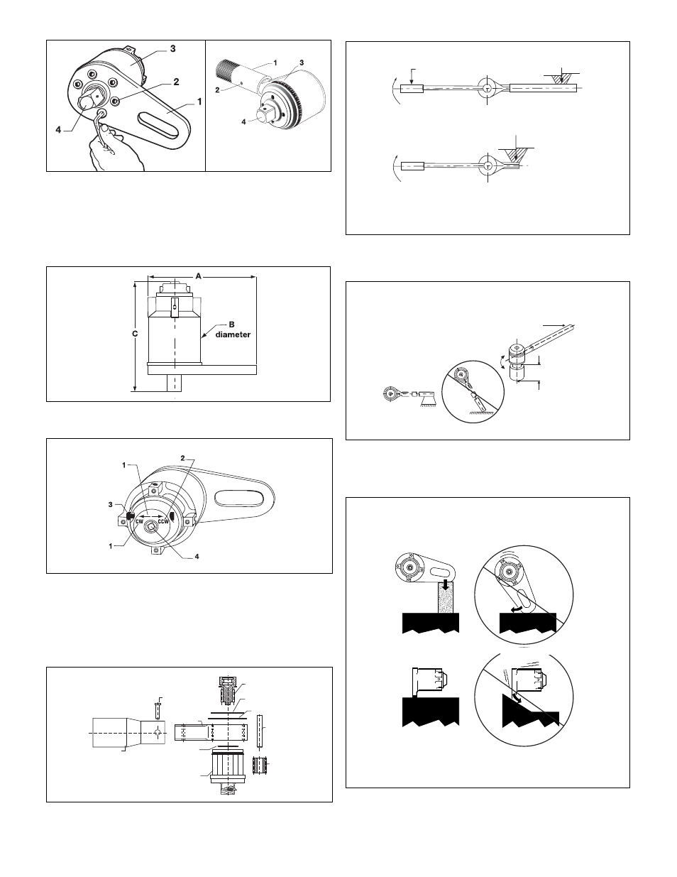
Figure 1, Changing the Reaction Plate
1. Reaction Plate / Reaction Bar
2. Socket Head Cap Screws
3. Torque Multiplier
4. Controlled-Shear Output Square Drive
Fig. 2, Torque Multiplier Dimensions
Fig. 3, Input End Detail (shown set for CW rotation)
1. Rotational direction indicators
2. Neutral positioning set screw
3. Selector pawl
4. 1/2-inch female input square drive
Fig. 4
Fig. 5, Reaction forces increase closer to the multiplier
Fig. 6, Minimize bending moments created by the torque
multiplier's reaction
Fig. 7, Keep reaction anchor perpendicular to the reaction
point.
Reaction Bar
Clevis Pin
Input Pinion
Retaining Ring
Circular Shim
Dowel Pin
Planet Gear
O-Ring
Gear Cage
Assembly
Ring Gear
Torque Wrench
2,400 lbs.
Reaction at end of standard reaction
Reaction on multiplier's reaction anchor
is opposite direction to input rotation
Keep torque
reaction at right
angle to tool.
Keep this distance
as short as possible
to reduce the
bending moment,
caused by the
torque reaction
6,360 lbs.
CORRECT
INCORRECT
CORRECT
INCORRECT