Can communication – ElmoMC SimplIQ Digital Servo Drives-Whistle Installation Guide User Manual
Page 47
Whistle and Tweeter Installation Guide
Installation
MAN-WHTWIG (Ver. 1.604)
47
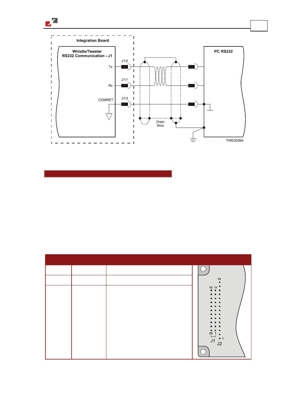
Figure 30: RS-232 Connection Diagram
3.12.2. CAN Communication
Notes for connecting the CAN communication cable:
Connect the shield to the ground of the host (PC). Usually, this connection is soldered
internally inside the connector at the PC end. You can use the drain wire to facilitate
connection.
Ensure that the shield of the cable is connected to the shield of the connector used for
communications. The drain wire can be used to facilitate the connection.
Make sure to have a 120 Ω resistor termination at each of the two ends of the network
cable.
The Whistle and Tweeter's CAN ports are non-isolated.
Pin (J1) Signal
Function
Pin Positions
20
CAN_GND
CAN ground
21
CAN_L
CAN_L busline (dominant low)
22
CAN_H
CAN_H busline (dominant high)
Table 12: CAN - Pin Assignments