Connecting main power, Auxiliary supply (for drive logic) – ElmoMC SimplIQ Digital Servo Drives-Whistle Installation Guide User Manual
Page 27
Whistle and Tweeter Installation Guide
Installation
MAN-WHTWIG (Ver. 1.604)
27
3.7.2.
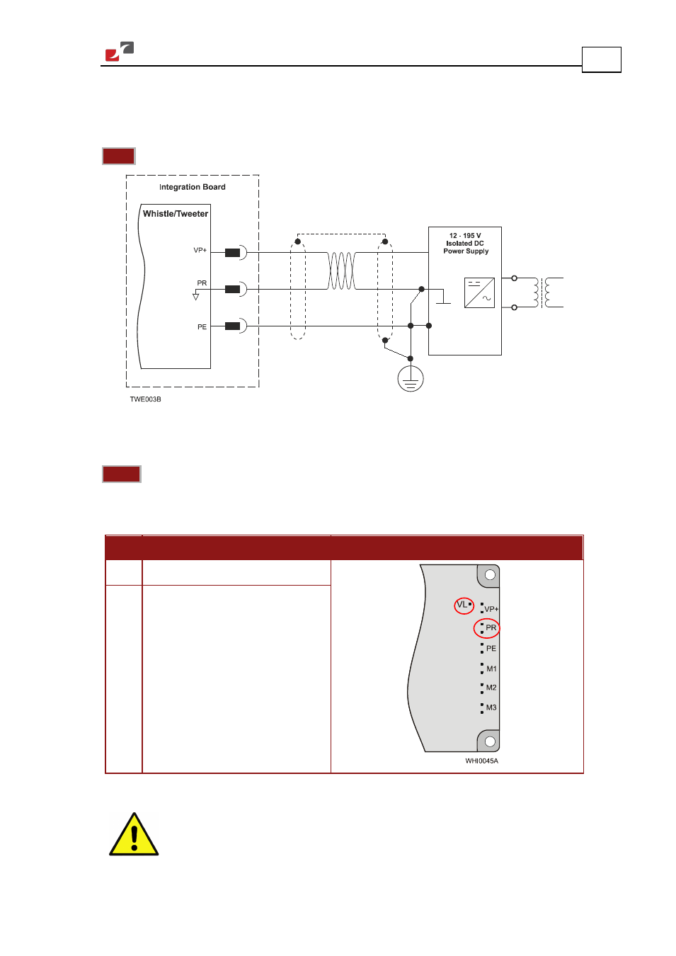
Connecting Main Power
Connect the VP+, PR and PE pins on the Whistle and Tweeter in the manner described in
Section 3.5 (Integrating the Whistle or Tweeter on a PCB).
Note:
The source of the 12 to 195 VDC Main Power Supply must be isolated.
Figure 7: Main Power Supply Connection Diagram
3.8. Auxiliary Supply (for Drive Logic)
Notes:
The source of the 12 to 95 VDC Auxiliary Supply must be isolated.
Connect the VL and PR pins on the Whistle and Tweeter in the manner described in Section 3.5
(Integrating the Whistle or Tweeter on a PCB).
Pin Function
Pin Positions
VL
Auxiliary Supply Input
PR
Supply Input Return
Table 3: Auxiliary Supply Pins
Caution:
Power from the Whistle and Tweeter to the motor must come from the Main
Supply and not from the Auxiliary Supply.