Det-Tronics Mac - w/Supercard User Manual
Page 43
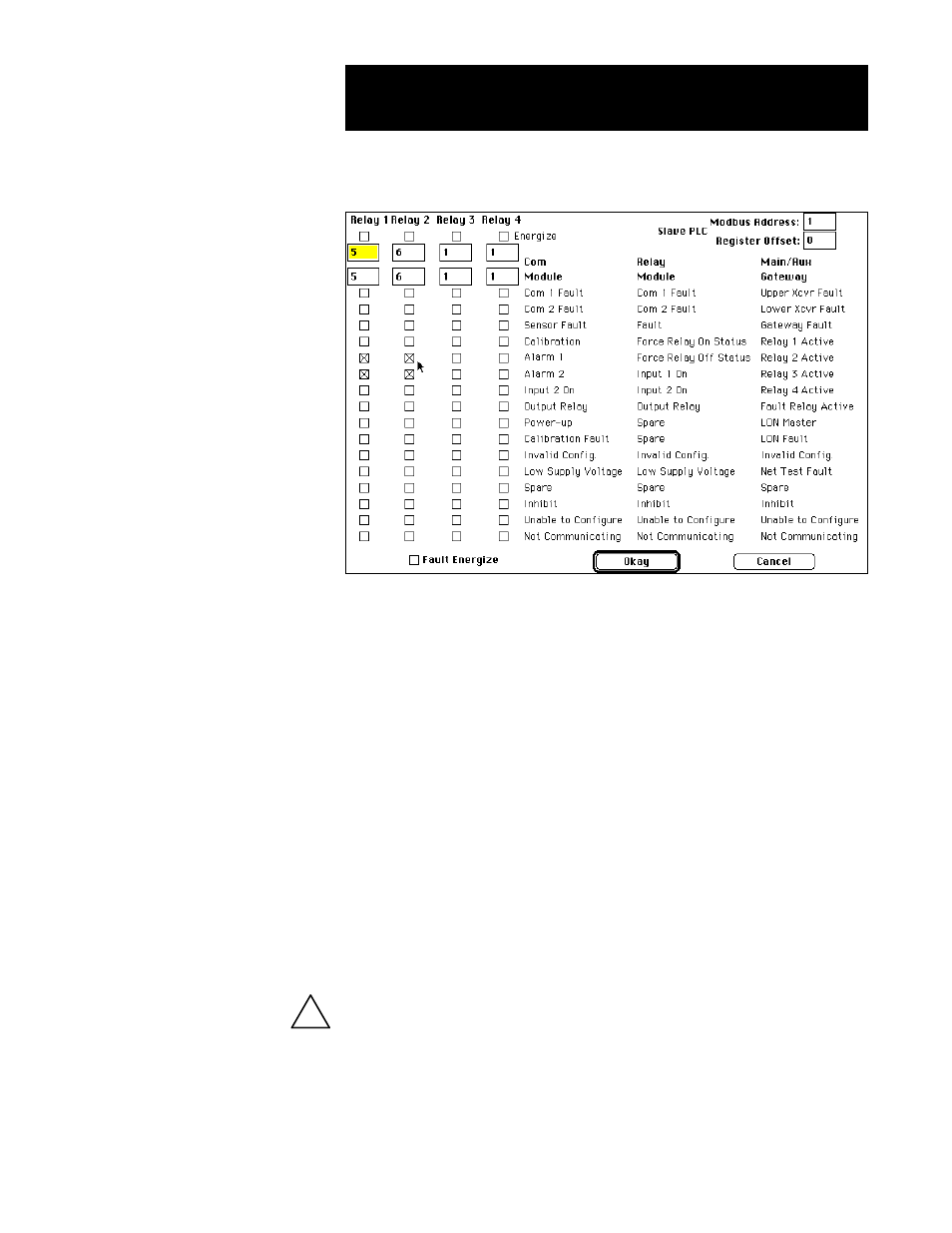
4. To configure the gateway relays, select Modify Relays. The
Gateway relay configuration screen is displayed:
5. The upper right area of the screen has two entries relating to
“Slave PLC” operation. When the gateway is configured so its
Port “0” is a Modbus RTU Master (to feed information to a PLC),
the Modbus Address and register offset may need to be adjust-
ed. The default values are MB address “1” and an offset of “0.”
Changing the PLC address (1 – 247) is used to ensure the gate-
way sends its data to the right PLC. The offset determines where
in the “40,000” register memory the data is placed. Normally
the gateway starts placing data in a Slave PLC’s memory at
40,001. If an offset of “100” were specified, it would start at
40,101.
6. Configure the gateway relays.
Gateway relay configuration involves selecting a range of points
(communication modules and their associated devices), which will
be monitored for any of the fault/alarm conditions listed. Any
fault/alarm that has been selected will cause the gateway relay to
energize/de-energize.
The point display screen provides a means of inhibiting a point. When a
point is inhibited, the gateway relay will not respond to any events or
alarms generated by a particular point. However, events configured in
the OIS will still respond.
Gateway Relay Configuration
2.30
95-8434
!
A1796