Device repair and return – Det-Tronics OPECL Infrared Hydrocarbon Gas Detector User Manual
Page 28
26
95-8556
10.1
noTe
If the replacement module is a receiver and is
used in an eQP system, it will have Lon address
switches that must be set. Set the switches on
the new module the same as the switches on
the module being replaced
before installing the
module into the bulkhead.
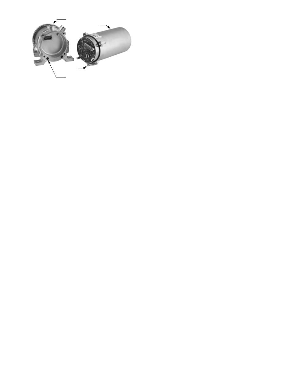
5. Line up the two pins on the replacement module with
the two holes in the bulkhead and insert the module
straight into the bulkhead. See Figure 24.
6. Insert and tighten the four flange bolts in an
opposing consecutive order in two stages — first
partially tighten all four bolts equally, and then
fully tighten each bolt in an opposing order to 40
inch-pounds (4.5 Nm) of torque. Bolts are M6 per
ISO 965 with M5 head, SST with a yield stress of 448
N/mm
2
(65.00 PSI) minimum.
CaUtIon
Flange bolts are critical to maintaining the
flameproof properties of the oPeCL. If
replacement flange bolts are needed, DeC spare
part number 007167‑001 must be used in order to
maintain the integrity of the enclosure. The use of
any other bolts will void the ex d certification of the
oPeCL.
7. When all equipment has been properly installed,
ensure that system alarms are appropriately
bypassed and apply power to the system.
8. Perform the alignment procedure as previously
described in this manual.
Important
If the oPeCL module had an aperture installed,
install the aperture before performing the
alignment procedure (install apertures on the
transmitter, not on the receiver). If the separation
distance is between 5 and 30 meters and signal
saturation is indicated after completion of the
Basic Alignment procedure, an aperture will
be required (even if no aperture was originally
installed). Refer to the "Aperture Kit for Short
Range Applications" section in this manual for
complete information regarding apertures.
9. Perform a zero calibration of the detector.
10. Upon completion of zero calibration, verify proper
operation by performing an “optical test film
test” and also a “beam block test” as previously
described in this manual.
noTe
Replacement receiver modules are furnished from
the factory with default configuration settings. If
the oPeCL system has had any configuration
changes in the field, the new receiver will require
changes to configuration parameters using a
HART communicator or a FlexVu UD10 display unit
(use S3 software for eQP models).
11. Restore system alarms (remove bypass).
dEvicE REpaiR and REtuRn
The Open Path Eclipse IR Hydrocarbon Gas Detector
is not designed to be repaired in the field. If a problem
should develop, first carefully check for proper wiring,
programming and calibration. If it is determined that the
problem is caused by an electronic failure, the device
must be returned to the factory for repair.
Prior to returning devices, contact the nearest local
Detector Electronics office so that a Return Material
Identification (RMI) number can be assigned. a
written statement describing the malfunction must
accompany the returned device or component to
assist and expedite finding the root cause of the
failure.
Pack the unit properly. Always use sufficient packing
material. Where applicable, use an antistatic bag as
protection from electrostatic discharge.
noTe
Inadequate packaging that ultimately causes
damage to the returned device during shipment
will result in a service charge to repair the damage
incurred during shipment.
Return all equipment transportation prepaid to the
factory in Minneapolis.
OPECL MODULE
BULKHEAD
ALIGNMENT
PIN (2)
TO INSTALL REPLACEMENT MODULE, LINE UP
PINS (2) WITH HOLES IN BULKHEAD AND
INSERT MODULE FULLY INTO BULKHEAD.
A2500
Figure 24—OPECL Module Removed from Bulkhead