Det-Tronics OPECL Infrared Hydrocarbon Gas Detector User Manual
Page 15
13
95-8556
10.1
pOWER WIRINg SIzE aND maxImUm lENgTh
1. To ensure proper operation, OPECL power terminals
(terminals 1 and 2 for Rx and Tx) and 4-20 mA
terminals (terminals 6 and 7 for Rx) must receive 18
Vdc minimum. 24 Vdc is recommended. Terminals
1 and 4, and terminals 2 and 5 on the OPECL Rx are
internally connected (see wiring diagrams).
2. Always determine voltage drops that will occur to
ensure that 24 Vdc is delivered to the OPECL.
3. Normally, nothing smaller than 18 AWG (1.0 mm
2
)
is recommended by Det-Tronics for OPECL power
cabling.
Wire size requirements are dependent upon power
supply voltage and wire length.
The maximum distance between the OPECL detector
and its power supply is determined by the maximum
allowable voltage drop for the power wiring loop. If the
voltage drop is exceeded, the device will not operate.
To determine the maximum power loop voltage drop,
subtract the minimum operating voltage for the device
(18 Vdc) from the minimum output voltage of the power
supply.
To determine the actual maximum wire length:
1. Divide the maximum allowable voltage drop by the
maximum current draw of the OPECL (0.35 A),
2. Divide by the resistance of the wire (ohms/foot value
available in wire manufacturer’s specification data
sheet),
3. Divide by 2.
For example: Consider an installation using 18 AWG
wiring with a power supply providing 24 Vdc.
Power supply voltage = 24 Vdc,
OPECL minimum operating voltage = 18 Vdc
24 – 18 = 6 Vdc
Maximum Voltage Drop = 6
Maximum Current = 0.35 A
Wire Resistance in Ohms/Foot = 0.006523
6 ч 0.35 ч 0.006523 ч 2 = 1314 feet
OpTIONal RElayS
Optional relay contacts are “dry”, meaning that the
installer must provide the voltage to the common
terminal of the relay output.
AC voltage should not be switched directly using the
OPECL relays. The use of an external relay is required if
AC voltage must be switched by the OPECL relays.
In order to change alarm relay settings from the factory
default settings, it is recommended to utilize a HART
Field Communicator. Contact the factory for further
assistance.
noTe
Refer to “Alarm Relays” in the Specifications section
of this manual for important information regarding
alarm relays.
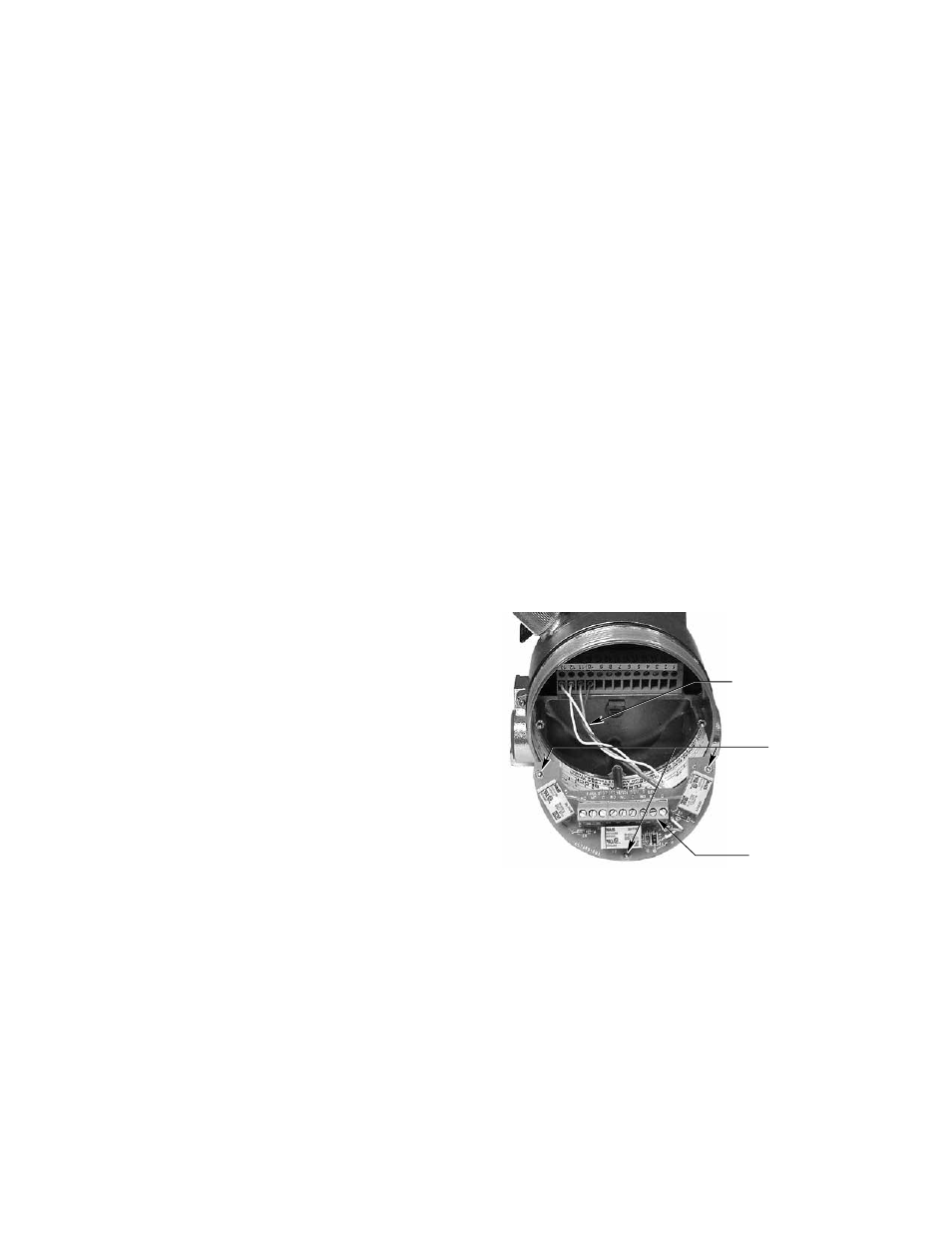
The relay board must temporarily be removed from
the OPECL termination compartment to connect the
relay output field wiring cables. After the relay wiring
is connected, re-install the relay board using the three
captive screws. Refer to Figure 7.
Note: Relays are not available on EQP models.
FACTORY INSTALLED WIRING
TO RELAY BOARD
(DO NOT REMOVE)
CAPTIVE SCREWS (3)
RELAY TERMINAL BLOCK
A2133
Figure 7—OPECL Wiring Termination Compartment with Optional
Relay Board Removed