Det-Tronics OPECL Infrared Hydrocarbon Gas Detector User Manual
Page 21
19
95-8556
10.1
8. Slowly adjust the receiver module left/right as
required using the horizontal adjustment bolts until
the telescope cross hairs are centered as close as
possible to dead center on the transmitter module
window. Tighten the horizontal adjustment bolts and
locking nuts so that no movement will occur.
9. Rotate the telescope alignment tool by 180° and
verify that the cross hairs are in the same position.
If the cross hairs are not in the same position, the
telescope alignment screws must be adjusted as
follows:
A. Adjust the telescope alignment screws until the
cross hairs are midway between the original
position (center of transmitter window) and the
current position (after the scope was rotated
180°). See Figure 20.
B. Return the scope to its original position (rotate
180°) and repeat steps 7 through 9 until correct
alignment is achieved.
noTe
no further adjustments are required when the
cross hairs are centered on the window with the
scope in both 180° positions.
10. Repeat the alignment procedure for the transmitter
module (steps 6 to 9).
11. Re-check the receiver for correct alignment (steps 6
to 9) and adjust as needed.
12. Remove the Telescopic Alignment Tool and re-install
the brow.
13. Bypass all external gas alarm devices that are
connected to the receiver outputs, and then apply
24 Vdc power to the modules.
14. Upon completion of warm-up mode (approximately
2 minutes or less), the receiver may display either
a green LED (normal mode) or a red LED (alarm
mode). An alarm condition is not abnormal and will
be cleared by performing a zero calibration.
15. For installations with module separation distances
between 5 and 30 meters, install the appropriate
aperture as described in the "Aperture Kit for Short
Range Applications" section.
16. Perform a zero calibration. (Refer to “Zero
Calibration” in the Calibration section of this
manual.) Any faults or alarms that may be present
as a result of the alignment process will be cleared.
17. When Basic Alignment and Zero Calibration have
been successfully completed, a green LED should
be displayed on the Rx module and the analog
signal output level should be 4.0 milliamperes.
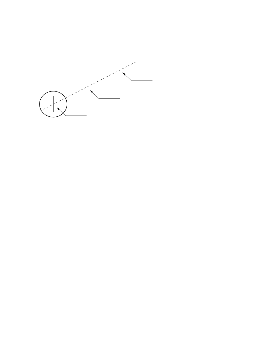
POSITION A = ORIGINAL ALIGNMENT
POSITION B = CROSS HAIR POSITION AFTER ROTATING SCOPE 180°
POSITION C = MIDWAY BETWEEN POSITION A AND B
STEP 1: CENTER CROSS HAIRS ON TARGET USING
ADJUSTMENT BOLTS ON MOUNTING PLATE
(POSITION A).
STEP 2: ROTATE SCOPE 180°. ALIGNMENT
ERROR CAUSES CROSS HAIRS TO
MOVE TO POSITION B.
STEP 3: ADJUST ALIGNMENT SCREWS ON SCOPE
TO PLACE CROSS HAIRS AT POSITION C.
STEP 4: ROTATE SCOPE 180° TO ORIGINAL POSITION.
STEP 5: REPEAT STEPS 1 TO 4 UNTIL THE UNIT IS
CORRECTLY ALIGNED.
A2314
Figure 20—OPECL Alignment using the Telescope Alignment Tool