Dakota Ultrasonics MVX User Manual
Page 68
Dakota Ultrasonics
64
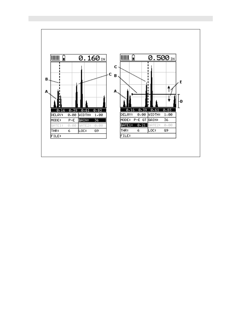
SURFACE NOISE PROBLEM
NO GATE
W/GATE
The diagrams above illustrate a typical surface noise condition. Refer to the NO
GATE diagram: (A) refers to the noise in front of the actual back wall signal (C).
Notice that without a gate activated, the MVX is detecting on the noise (A) as shown
at point (B). However, the true measurement should be taken at point (C). Given the
threshold and gain levels the MVX is currently set to in the NO GATE diagram, the
amplitude from the noise is sufficient enough to cause the MVX to detect, or measure
the noise rather than the true back wall thickness (C). Therefore, the MVX is making
an incorrect reading at point (B).
Now refer to the W/GATE diagram. The horizontal line at the top of (D), is GATE1.
The start point of GATE1 has been adjusted to just beyond the noise (A) so that the
MVX ignores the noise and detects the true back wall (C). Note: the MVX will only
detect on signals that are located inside the dimensions of GATE1 (B). Therefore,
the MVX cannot see (A) at all, with respect to the starting point of (B). Also notice,
the THR (threshold) level is the height of the distance (D) from the baseline. Zero
threshold is indicated by the bottom of the range (D), and THR: 6 (threshold) is
indicated at the top of the range at (D). Therefore, the vertical height of GATE1 is the
THR (threshold) level. The threshold level can be increased to decrease sensitivity,
or decreased to increase sensitivity.
If the threshold level was increased in the NO GATE diagram, so that the level was
higher than the amplitude of the noise (A), the MVX would have detected on the true
back wall (C). Alternatively, if the gain level was decreased, the signal amplitude of
the noise (A) would have decreased below the threshold level, and the MVX would