Dakota Ultrasonics MVX User Manual
Page 112
Dakota Ultrasonics
108
12.2 Flaw Mode View
Flaw Mode View
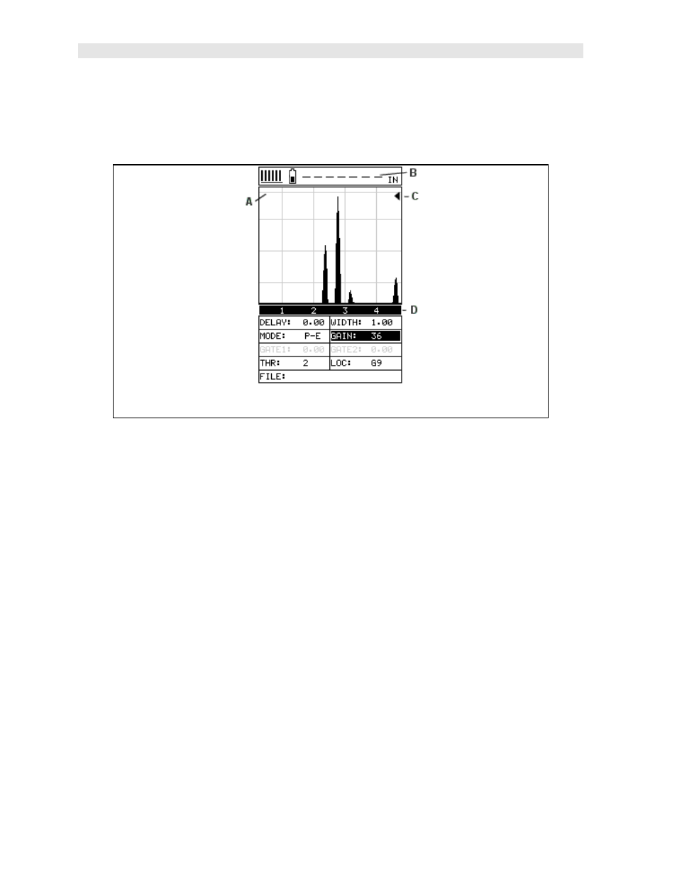
Refer to the diagram above. The grey grid line, point (A), corresponds to 100% FSH
(Full Screen Height). The other grid lines correspond to 25% amplitude increments,
in order to calibrate the MVX in this mode. The digital thickness value has been
replaced by dashed lines at point (B). The digital thickness value is not applicable
while operating in this mode. Notice at point (D), the vertical grid lines have simply
been given quadrant numbers. Again, this is because the grid lines do not
correspond to a thickness value based on the delay and width of the screen. Finally,
point (C) is the peak hold symbol - carrot. The carrot is only displayed if the flaw
mode is set to “peak”. The peak hold position represents the highest amplitude
obtained during the scan. Pressing the CLR key will reset the peak hold position to
zero.
12.3 Enabling Flaw Mode
Note: This mode is only available in firmware version 1.5 forward. Gauges that were
purchased prior to this version will need to be flash programmed with the latest
revision firmware. Upgrades are available on our website at no charge. However,
gauges purchased prior to this revision will also need a slight hardware modification.
Please contact Dakota Ultrasonics for additional information regarding the