Dakota Ultrasonics MVX User Manual
Page 49
45
CHAPTER SEVEN
USING THE A-SCAN & B-SCAN DISPLAYS
A key feature of the MVX is the waveform display. The waveform is a graphical
representation of the sound reflections returning to the transducer. Consider
standing at the base of a canyon and screaming “Hello There”. After a brief delay,
you will here multiple echoes, “Hello There’s” repeated back to you. The waveform
display shows the amplitude of the signal received on the vertical (Y) axis and time
(shown in units of thickness) on the horizontal (X) axis.
The waveform display is very useful for viewing and adjusting the location of the
gates. The gates are typically used to eliminate potential surface noise by adjusting
the starting point in single echo modes, for multi echo measurement modes, as well
as to adjust the threshold (sensitivity) in either mode. The waveform display is also
very useful for locating pits and internal flaws in materials.
The B-Scan display is also very useful when scanning surfaces and viewing the cross
section of the test material. It provides a convenient way of profiling the blind
surfaces during a scan. The B-Scan display is also equipped with a scan bar
representing the overall thickness. The scan bar gives the user a visual indication
when a flaw or defect passed over during the scan process. The scan bar will deflect
off of the defect and return back to the overall thickness. Visually, this is much easier
to notice than watching for changes in the digital value displayed. The scan bar has
also been included in the large digits display mode for the same purpose.
Note: The following chapter outlines some of the fine adjustment features of the
MVX. The MVX has four different display options (RF A-Scan, Rectified A-Scan, B-
Scan, and Large Digits). We’ll take a better look at these options in this chapter.
Note: In order to recall and use the new adjustments made to the MVX at a later
time, the user must save the modified settings in one of the setup locations prior to
powering off the unit. Refer page 100 for more information on setups.
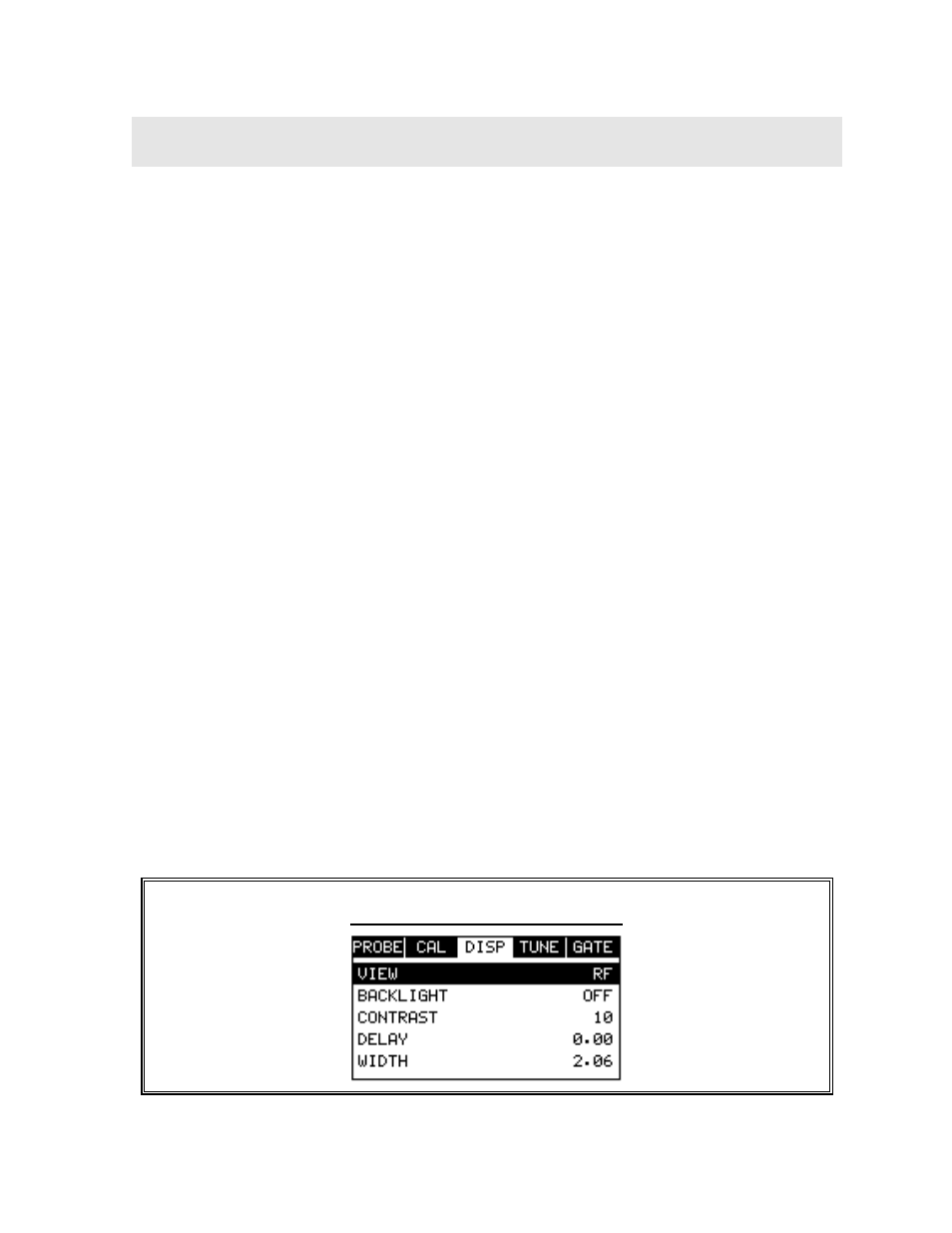
7.1 Selecting a Display Option
The following procedure outlines how to select or toggle display options:
Changing Display Options