4 transmitter cable connections, 1 transmitter housing cable entry, 4 transmitter cable connections -3 – CiDRA SONARtrac HD VF-100 User Manual
Page 43: 1 transmitter housing cable entry -3
Copyright © 2006 CiDRA Corporation
Page 8-3
20638-02 Rev 01
8.4
Transmitter Cable Connections
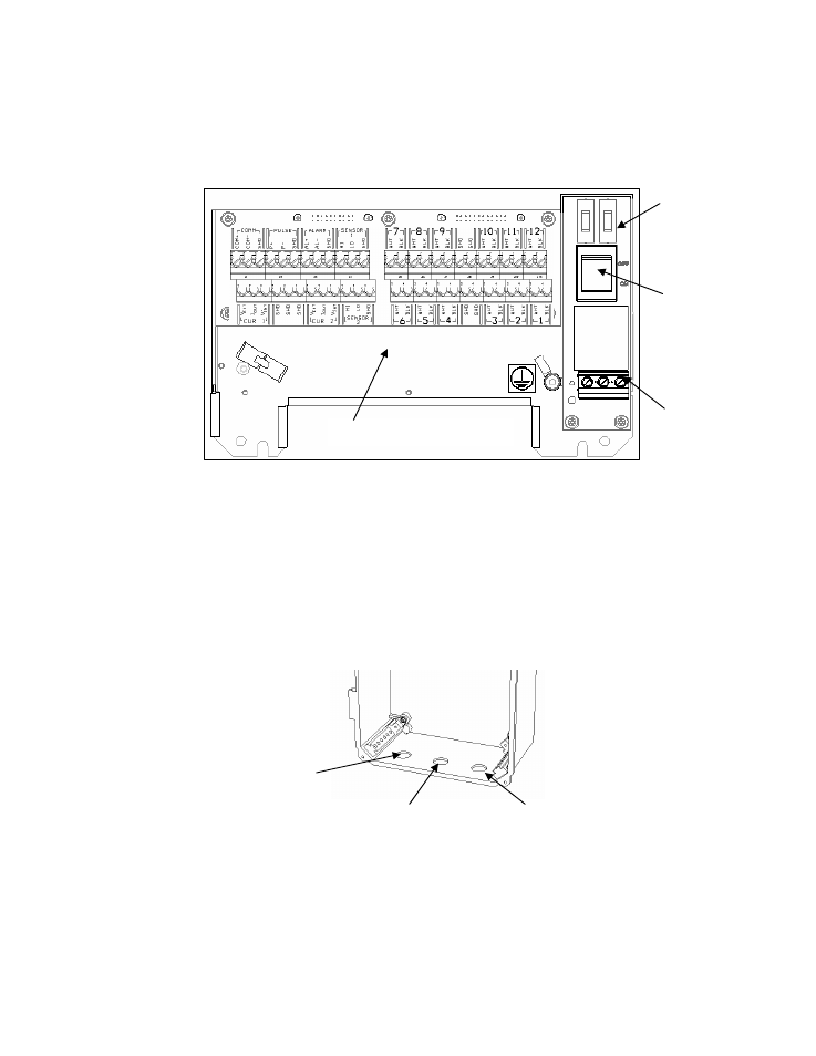
The following figure illustrates the basic power and signal connections
for the SONARtrac
TM
Flow Monitor. These are discussed in further
detail in the following sections.
Figure 33
Power and Signal Interconnects
8.4.1
Transmitter Housing Cable Entry
Power, sensor signal, and input /output signal cables enter the
transmitter housing through cable glands. The cable glands also
provide strain relief for the cables. Always ensure they are fully
tightened. The following figure illustrates where each of the cable
glands are installed.
Figure 34
Transmitter Housing Cable Gland Holes
Output & Sensor
cable gland hole
Sensor head to transmitter
cable gland hole
Power cable gland hole
Fuses
Optional
power
switch
Power
connector
I/O and sensor connects