CiDRA SONARtrac HD VF-100 User Manual
Page 30
Copyright © 2006 CiDRA Corporation
Page 7-13
20638-02 Rev 01
The following steps will help minimize this problem:
1. Visually look between the cover halves to ensure the cable is not
being pinched.
2. Once the cover halves are bolted in place and during installation of
the sensor band cable connector into the pre-amplifier through the
access cover, verify the sensor band cable is free and not pinched
between the cover halves.
3. If the cable is not free and appears to be pinched, remove the
sensor band cable from the pre-amplifier, unbolt the cover, free the
cable from between the cover halves and then re-install. Note this
on the installation report for future reference.
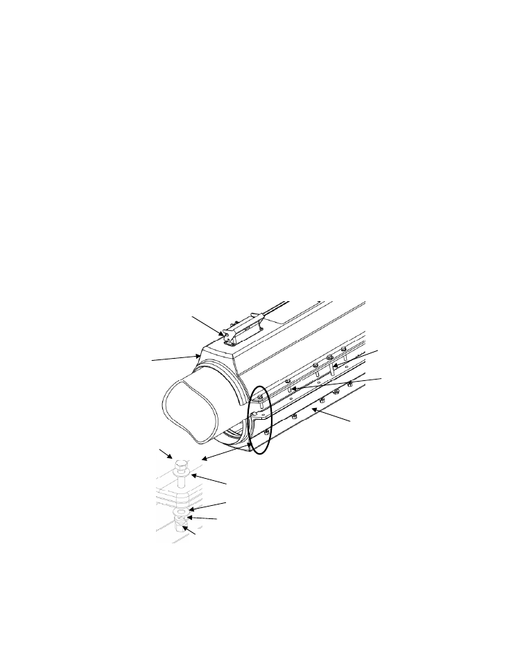
Refer to the following figure. Align the center alignment holes on the
sensor cover. Install a 3” long 3/8” diameter alignment bolt, with
washer under the bolt head, in center holes on both sides of the cover.
Install a washer and nut on the alignment bolts. Install a 5/16”-18 x
1.5” tin plated 316 SST bolt with washer into each of the 12 cover bolt
holes in the upper cover.
Figure 17
Sensor Cover Bolt Installation
Alignment
bolts
(2 places)
Cover bolt
assemblies
(12 places)
Upper cover
assembly
Lower cover
assembly
Bolt
Washer
Lock washer
Washer
Nut
Transmitter cable connector
socket
Cover bolt
assembly