Telnet to the switch, Connect through broadband router – AirLive SNMP-FSH2602MG User Manual
Page 69
AirLive SNMP-FSH2602MG User’s Manual
57
network. Then the Cable provider will assign the switch with a IP and Gateway. Go to the
console port management to find out what IP has been assigned to the switch.
When the configuration is finished, the Remote PC can access the switch by typing the
switch’s IP address on the Telnet.
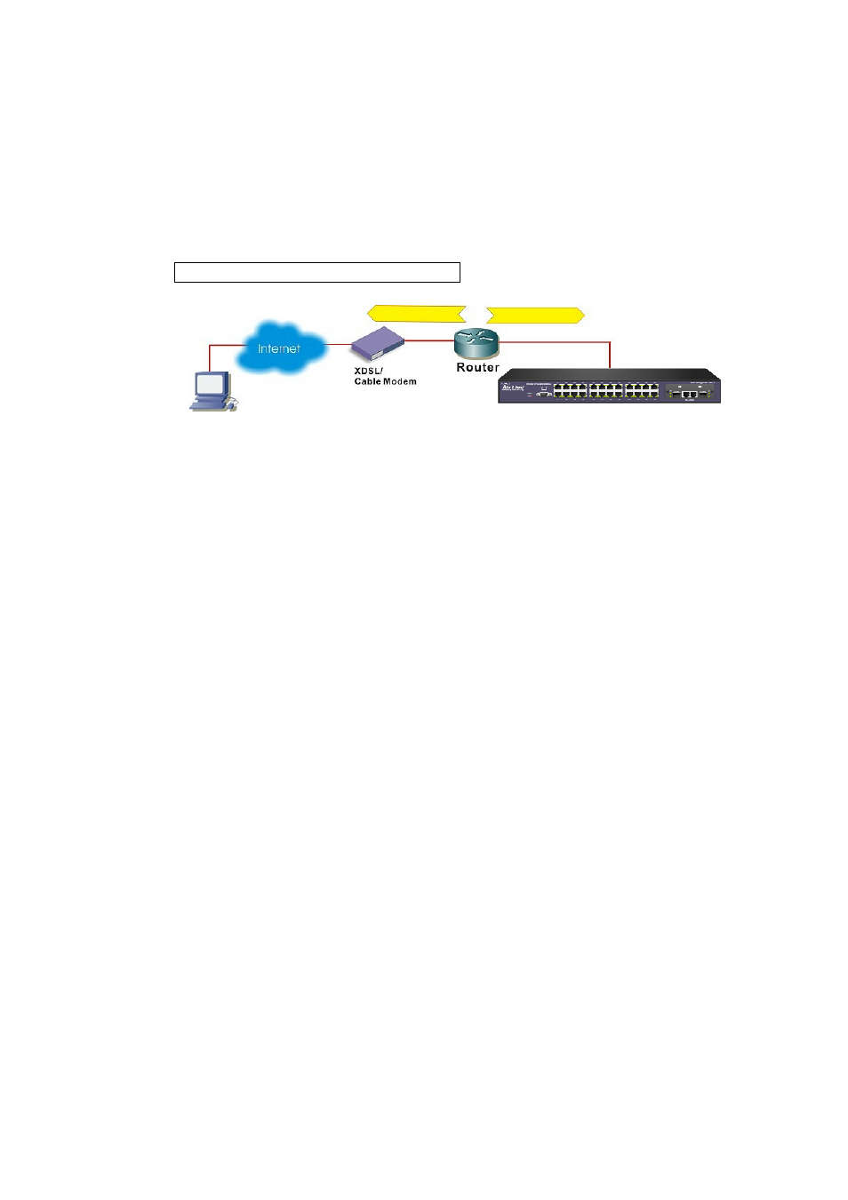
Connect through Broadband Router
Figure 5-3 Remote Management through Broadband Router
If you have an IP sharing router in the network, you can open a virtual server on the router
to allow the switch to be managed through Internet. This method is more recommended as
the broadband router provides natural fire wall protector from hackers.
In the diagram above, the router has the WAN (given by the ISP) port IP address
“201.100.1.5” and LAN port address “192.168.0.254”. The switch’s IP is “192.168.0.200”.
Please follow the instruction below to setup the router and switch for remote access:
On the Switch
On the IP setting, set the gateway to Router’s LAN port address 192.168.0.254
Please make sure the subnet mask is the same as the router’s.
On the Router
Go to router’s Virtual Server setting and open the Telnet port (TCP Port 80) to the
switch’s IP address 192.168.0.200
If your router require enter the beginning and ending Port (from PortX to PortX), enter
80 for both.
Now the Remote PC will be able to access your switch by telneting to “201.100.1.5”.
Telnet to the switch
After you have properly configured the computer and switch’s IP, you can get into the telnet
management by the following steps:
Step 1
: Open your telnet program
Step 2
: type “o
Step 3
: When prompt for User’s name and Password, enter the following information:
User’s
Name:
admin
Password:
123
Remote PC
Switch IP: 192.168.0.200
192.168.0.254
201.100.1.5