Hardware overview, Front panel, The rear & side panel – AirLive SNMP-FSH2602MG User Manual
Page 18
AirLive SNMP-FSH2602MG User’s Manual
6
Hardware Overview
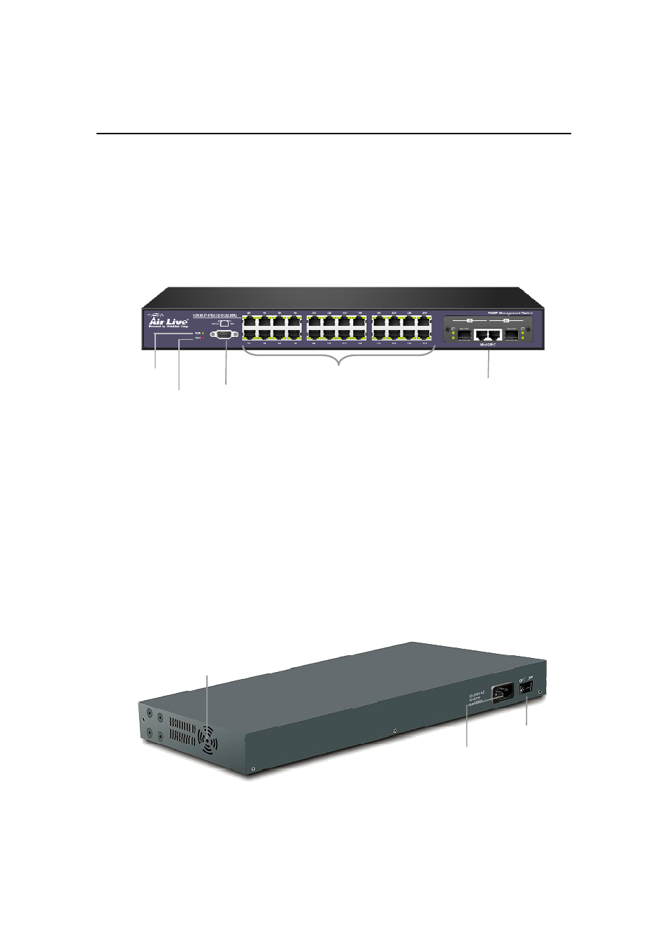
Front Panel
The front panel is where you can find the twenty-four 10/100Mbps station ports, the module
slot, console port, and the LED indicators. For the technical specifications of the ports,
please refer to Appendix A, Product Specifications for detailed information. For detailed
explanation of the LED lights, please refer to chapter 3 “LED Indicators”.
DIAG LED:
The DIAG LED indicator will blink for 100 seconds during power-up to
indicate the process of diagnostic test. The switch will function only after the power-on
diagnostic test is completed. The DIAG LED will stay solid green after the test is
completed.
Console Port:
The console port is where you can connect the switch (via a RS-232
cable) to a computer for smart console management. Please refer to chapter 5
“Console Port and Telnet management” for more information.
mini-GBIC Port :
2 pair ports of RJ-45 (1000Base-T/SX/LX) and mini-GBIC with
auto-detection
The Rear & Side Panel
The rear panel and side panel is where you can locate the power switch, AC power
connector, and cooling fans.
Fig. 2-3 Rear & Side Panel
Power Switch
Power Connector
Cooling FAN
Power LED
DIAG LED
Station Ports
Console Port
1000BaseT/ miniGBIC port