Ista, Comprobación, Mantenimiento – Snorkel XRT33-sn2300+CE User Manual
Page 13: Preventivo, Aintenance, Eferencias, Nforme, Locking, Levating, Ssembly
64
Plataforma de trabajo XRT
L
ISTA
DE
COMPROBACIÓN
DE
MANTENIMIENTO
PREVENTIVO
R
EFERENCIAS
DE
MANTENIMIENTO
PREVENTIVO
I
NTERVALO
Diario = cada turno o cada día
50 h/30 d = cada 50 horas ó 30 días
250 h/6 m = cada 250 horas ó 6 meses
1000 h/2 a = cada 1000 horas ó 2 años
S = Sí/aceptable
N = No/no aceptable
R = Reparada/aceptable
I
NFORME
DE
MANTENIMIENTO
PREVENTIVO
Fecha: ___________________________________
Propietario: _______________________________
Nº de modelo: _____________________________
Número de serie: ___________________________
Servicio efectuado por: ______________________
Intervalo de servicio: ________________________
COMPONENTE
INSPECCIÓN O SERVICIOS
INTERVALO
S
N
R
Batería
Comprobar el nivel de electrólito.
Diario
Comprobar la gravedad específica.
6 m
Limpiar el exterior.
6 m
Comprobar el estado del cable
de la batería.
Diario
Limpiar los terminales.
6 m
Aceite del
motor y filtro
Comprobar el nivel y estado.
Diario
Comprobar si hay fugas.
Diario
Cambiar filtro de aceite.
250 h
Sistema de
combustible
del motor
Comprobar el nivel del combustible.
Diario
Comprobar si hay fugas.
Diario
Sustitución del filtro del combustible.
6 m
Comprobar el depurador de aire.
Diario
Sustituir el elemento depurador de aire
(diesel).
Anual
Comprobar la línea de aire de admisión
(diesel).
6 m
Refrigerante
del motor
Comprobar el nivel de refrigerante
(con motor frío).
Diario
Sustitución de refrigerante.
2 a
Comprobar mangueras y abrazaderas.
6 m
Aceite
hidráulico
Comprobar el nivel del aceite.
Diario
Cambiar el filtro.
6 m
Drenar y sustituir el aceite.
2 a
Sistema
hidráulico
Comprobar si hay fugas.
Diario
Comprobar las conexiones de
las mangueras.
30 d
Comprobar el desgaste exterior de
las mangueras.
30 d
Sistema
hidráulico de
emergencia
Poner en marcha la válvula de bajada de
emergencia y comprobar su
funcionamiento.
Diario
Controles de
la plataforma
Comprobar el funcionamiento del
interruptor.
Diario
Cable de
control
Comprobar el exterior del cable en busca
de estrangulamientos, torsiones o
desgaste.
Diario
Cubierta y
raíles de la
plataforma
Comprobar el par de torsión correcto
de los pasadores.
6 m
Comprobar si hay grietas en
las soldaduras.
Diario
Comprobar el estado de la cubierta.
Diario
Neumáticos
Comprobar si hay daños.
Diario
Comprobar las tuercas de aletas (par de
torsión 122 N·m [90 lbs.-pies]).
6 m
Bomba
hidráulica
Limpiar.
30 d
Comprobar si hay fugas en las superficies
de unión.
30 d
Comprobar si hay fugas en las conexiones
de mangueras.
Diario
Comprobar que el par de torsión de los
tornillos de montaje sea el correcto.
6 m
Motores de
impulsión
Comprobar el funcionamiento y fugas.
Diario
Sistema de
cambio de
dirección
Control del par de torsión correcto de
tornillería y conectores.
6 m
Engrasar pasadores de pivote.
30 d
Lubricar el vástago maestro.
30 d
Comprobar si hay fugas en el cilindro
de dirección.
30 d
Conjunto de
elevación
Inspección de grietas estructurales.
Diario
Comprobar el desgaste en el punto
de pivotación.
6 m
Comprobar el par de torsión apropiado
de los tornillos de giro del pasador
de montaje.
6 m
Comprobar el doblado de los brazos
de elevación.
6 m
Chasis
Comprobar si hay pinchazos o desgaste
de las mangueras.
Diario
Controlar el par de torsión correcto de
montaje de componentes.
6 m
Comprobar si hay grietas en las
soldaduras.
Diario
Sensor de
inclinación
Comprobar el funcionamiento.
6 m
Cilindro de
elevación
Comprobar el desgaste de la varilla
del cilindro.
30 d
Comprobar el par de torsión apropiado
de los tornillos de giro del pasador
de montaje.
6 m
Comprobar si hay fugas en las juntas.
30 d
Inspeccionar el desgaste de pivotes.
6 m
Control del par de torsión correcto de los
conectores.
6 m
Unidad
completa
Comprobar y reparar daño por colisión.
Diario
Comprobar el par de torsión correcto
de los pasadores.
6 m
Comprobar si hay corrosión,
retirar y pintar.
6 m
Lubricar.
30 d
Etiquetas
Control de estado de legibilidad o falta de
etiquetas y reemplazar.
Diario
COMPONENTE
INSPECCIÓN O SERVICIOS
INTERVALO
S
N
R
13
XRT Work Platform
M
AINTENANCE
B
LOCKING
THE
E
LEVATING
A
SSEMBLY
B
RACE
I
NSTALLATION
1. Park the work platform on a firm, level surface.
2. Pull Chassis EMERGENCY STOP Switch to the ON position.
3. Pull Platform EMERGENCY STOP Switch to the ON position.
4. Turn Platform Controls Key Switch to ON.
5. Turn Platform/Chassis switch to CHASSIS.
6. Push and hold the START button to start the engine. Release the
button once the engine starts.
7. Push the THROTTLE button, and push the RAISE button to ele-
vate the platform until the Scissor Brace can be rotated to the ver-
tical position.
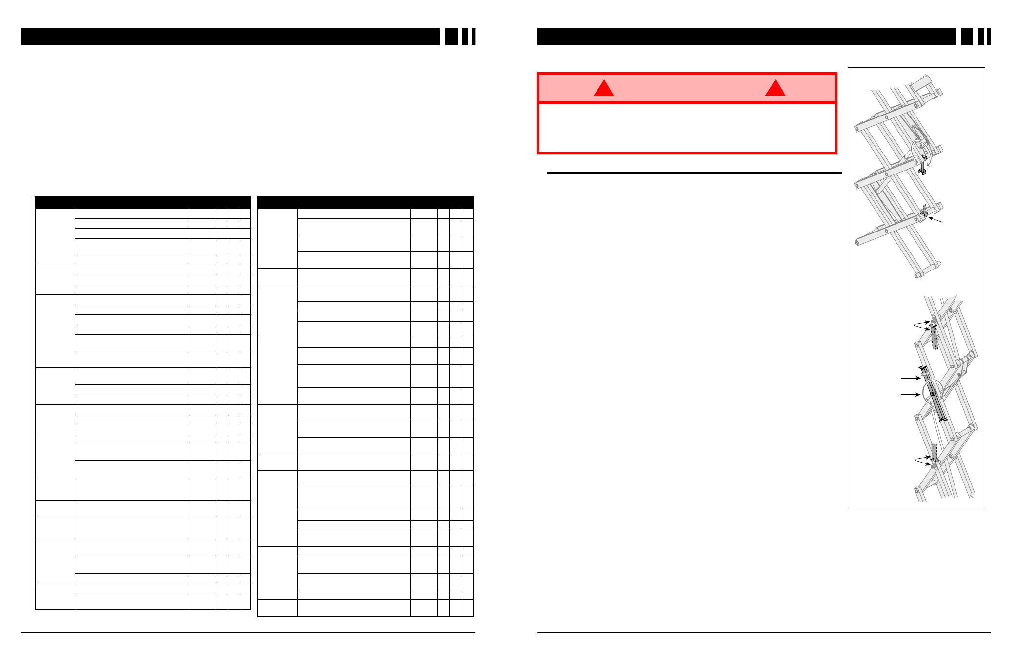
8. XRT27 – From the rear of the machine, lift the Scissor Brace from
its stowed position. Rotate upward and outward, then down until it
is hanging vertically below its attachment point.
9. XRT33 – From the left side of the machine, pull the locking pin
securing the brace. Rotate the Scissor Brace counterclockwise
until it is in the vertical position.
10. Lower the platform by pushing in on the Chassis Controls LOWER
button and gradually lower the platform until the Scissor Brace is
supporting the platform.
B
RACE
R
EMOVAL
1. Using the Chassis Controls, gradually elevate the platform until
the Scissor Brace is clear.
2. XRT27 – Rotate the Scissor Brace outward and upward over its
mounting point until it rests in the stowed position.
3. XRT33 – Rotate the Scissor Brace clockwise until the locking pin
engages.
4. Lower the platform by pushing in on the Chassis Controls LOWER
button to completely lower the platform.
W A R N I N G
!
!
Never perform service in the elevating assembly area while the platform is
elevated without first blocking the elevating assembly.
DO NOT stand in elevating assembly area while deploying or storing brace.
DO NOT block elevating assembly with a load on the platform.
BRACE RESTS ON
WELDMENT WHEN IN
BLOCKING POSITION
ROTATE BRACE
CLOCKWISE
TO BLOCK
PIN RESTS ON
BRACE WHEN IN
BLOCKING POSITION
SCISSOR BRACE
IN REST POSITION
BRACE ROTATES
TO BLOCKING
POSITION
BRACE RESTS ON
PIN WHEN IN
BLOCKING POSITION
XRT27
XRT33
Figure 10: Blocking the Elevating
Assembly