Network, Network -3, Usm network – Class1 ES-Key-USM User Manual
Page 2: Class1
2
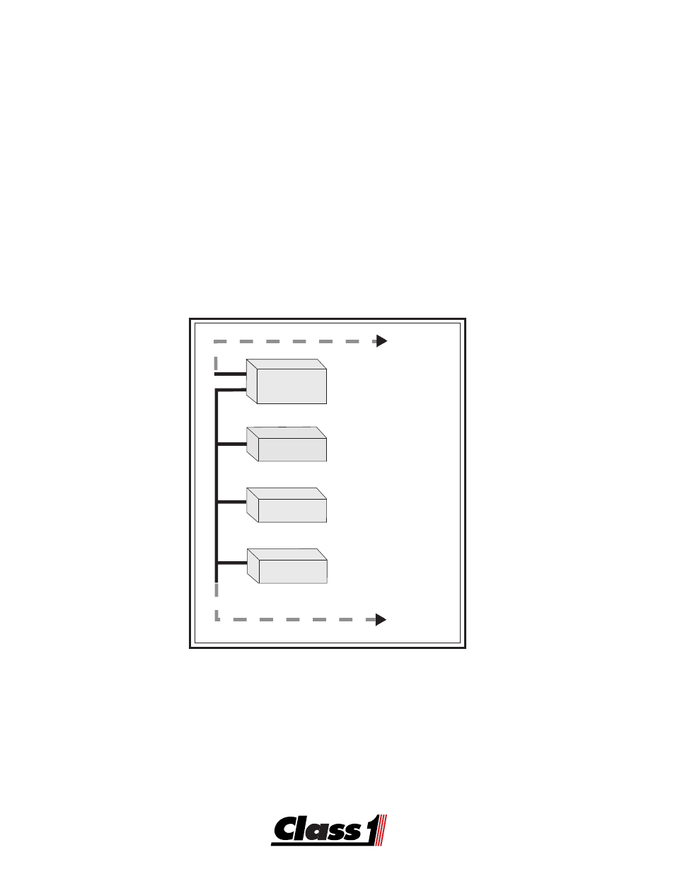
Control
Module
Switch
Module
Vocation
Module
Output
Module
Power Switching
to Loads
Main Controller
and
User Interface
Interface to
Switch Panel
Vocation Interlock
Trans/Engine
Interface
To other
J-1939 Devices
To other Devices
on the Management
Network Segment
USM Network
The
Class1
ES-K
ES-K
ES-K
ES-K
ES-Keeeeey
y
y
y
y
TM
TM
TM
TM
TM
Sy
Sy
Sy
Sy
Syst
st
st
st
stem
em
em
em
em
consists of several components that can be used in a vehicle
electrical system. The system is multiplexed using the Controller Area Network bus and the
SAE J-1939 protocol. An electrical database is used by the Control Module to operate the
vehicle electrical system. The
ES-K
ES-K
ES-K
ES-K
ES-Keeeeey
y
y
y
y
TM
TM
TM
TM
TM
Expr
Expr
Expr
Expr
Expres
es
es
es
ess
s
s
s
s
software allows you to create, read or modify
this database. Troubleshooting of the system is also accomplished with the software.
The Controller Area Network (CAN) has specific requirements that should be met for
maximum reliability.
Network modules communicate with each other through the J-1939 Controller Area Network.
Network
- 4 output tank level (5 pages)
- Digital Aerial Warning Display (6 pages)
- Digital Air Minder (8 pages)
- Digital Clock (1 page)
- Digital Display (35 pages)
- Flowminder 102046 - SSD Digital Flow Meter (9 pages)
- Digital Oxygen Remaining (6 pages)
- Digital Pressure Gauge (6 pages)
- Digital Tank Level Display (5 pages)
- Electrical System Manager (15 pages)
- Electronic Fire Commander (8 pages)
- ENFO III (4 pages)
- ENFO IV - 1 page (1 page)
- ENFO IV (10 pages)
- Engine status center (9 pages)
- Engine status OEM menu (3 pages)
- ESM3 (14 pages)
- Intelli Tank 4 light driver module (9 pages)
- Intelli Tank level display with drip empty (16 pages)
- Intelli-Tank (15 pages)
- Total System Manager (12 pages)
- Total System Manager (19 pages)
- Vernier Throttle for CAT- new (8 pages)
- Vernier Throttle for CAT (12 pages)
- Vernier Throttle for Cummins (9 pages)
- Digital Pressure Service & Calibration (5 pages)
- 109395 - ITL 4LT with 1-wire COM 106296 106299 - 1page (1 page)
- Throttle Information Reference (24 pages)
- ITL Tank Level Driver Module 107451 (9 pages)
- ITL Mini Remote Driver one-page_manual 112648 (1 page)
- Throttle Interface CAT 105216 (8 pages)
- Pump Throttle Electric Cotnrol Series 2 (14 pages)
- 107490 - UNI-Governor 107396 107269 software v 6 00 (38 pages)
- FoamLogix 2.1A & 1.7AHP REV E (96 pages)
- EZFill Foam Refill (46 pages)
- Digital speedometer (4 pages)
- 106759 - ITL 4LT with 1-wire COM 106296 106299 (18 pages)
- 114356 - ITL 4LT with 1-wire and CAN COM 113739 114378 (24 pages)
- 115355 - ITL 4LT with 1-wire and CAN COM 113739 114378 - Page (1 page)
- 117155 - TPG Governor - 117684 EXTERNAL (30 pages)
- 117155 - TPG Governor - 117685 (2 pages)
- 118253 - ITL40 108404-XX - Full (26 pages)
- 118252 - ITL40 118404-XX - Quick Start (1 page)
- 118712 - TPG+ Governor - 118710 (2 pages)