System logic – Class1 ES-Key-USM User Manual
Page 17
17
System Logic
The ES-Key System utilizes an electrical connection database for operation. This database
is written by the OEM and contains all the information necessary to operate the ES-Key
System for a specific vehicle. The system can be customized to the user’s needs without
changing the physical wiring or hardware. This database can be ‘read’ by the user and is an
‘as built’ wiring diagram that stays with the system.
Each ‘output circuit’ has three conditions of operation:
Multiplexing:
Two conditions of operation are available for each circuit.
These conditions can be logically ‘AND’ed (both conditions must be true) or
logically ‘OR’ed (either condition can be true) to each other.
Additionally, either or both of these conditions can use ‘NOT’ logic.
‘NOT’ logic simply means that the condition must be false for the system to
consider it true.
The conditions can be inputs or outputs from anywhere in the system.
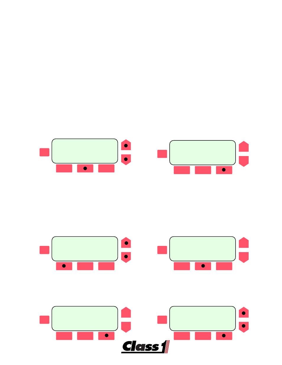
SCROLL
ESC
--SYSTEM OUTPUTS--
CIR:
Pump Panel Lgts
POWER MOD#0 OUT-01
[MNGT] [
MPLX
] [INTK]
SCROLL
ESC
MUX:
circuit name
1:
Condition 1 LOGIC
2:
Condition 2
[GO->1] [BACK] [
GO->2
]
Load Management:
Outputs can be load managed to sequence on and sequence off.
Outputs can be load managed to shed at a specific voltage level.
Outputs can be managed to operate in Mode A, Mode B or both.
Fire Service Mode A is typically Response and Mode B is Scene.
Outputs can be tied to a Staged input.
Staging for the fire service is typically the Warning Master Switch.
Interlocking:
Any output can be tied to any of several interlocks available from an ES-Key
Vocation Module.
SCROLL
ESC
System Outputs
CIR: PDM0 RLY 0
POWER MOD#0 OUT 0
[
MNGT
] [MPLX] [INTK]
SCROLL
ESC
MNG:PDM0 RLY 0
SEQUENCE:0 SHED:0
MODE B ONLY;STAGE:Y
[BACK] [
HELP
] [EDIT]
SCROLL
ESC
SCROLL
ESC
INTERLOCKS [
SCROLL
]
CIR:
Circuit Name
Pump Shift : ON
[BACK] [
NEXT
]
System Outputs
CIR: PDM0 RLY 0
POWER MOD#0 OUT 0
[MNGT] [MPLX] [
INTK
]