Solid state pdm – Class1 ES-Key-USM User Manual
Page 13
13
Solid State Modules use an integrated circuit driver to supply current to it’s loads. Outputs
are common bussed to system power and can deliver up to 7.5 Amps. Current levels above
two (2) amps can be used to indicate whether an output is ON or OFF. These modules use a
Hex switch for addressing and come in three (3) styles.
104434 Eight (8) output
PDM-8
104528 Six output Two input
PDM-(6/2)
104529 Four output Four input
PDM-(4/4)
Solid State Modules with inputs have polarity selectable inputs.
Any output can be made to flash, the first four inputs flash at one instance and the second
four flash at the opposite instance (anti-flash).
The flash rate can be configured to 75 FPM or 150 FPM.
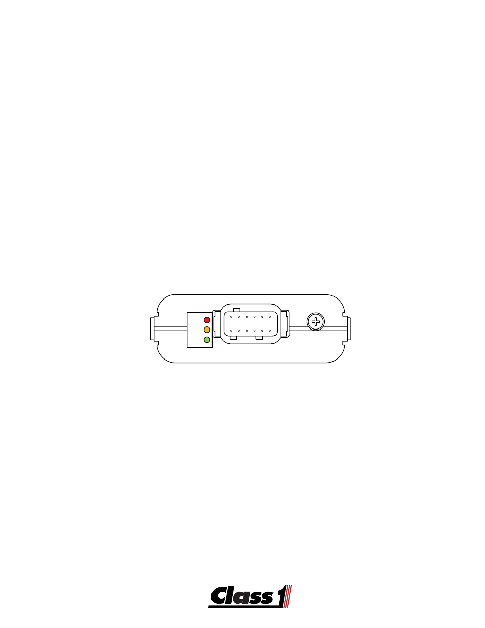
PWR
BUS
COM
7 8 9 10 11 12
6 5 4 3 2 1
Solid State PDM
The PWR LED indicates whether the system electronics have power or not.
The BUS LED indicates whether or not there is power for the output loads.
The green LED is on steady with good communications.
A slow flash rate indicates that communications are down.
A fast flash rate means that there is an address conflict with another module.
If the LED is off, communications to and from the module are noit present.