Burnham MPC User Manual
Page 55
55
c. Connect opposite end of L4006B Low Fire Hold
Control harness to right side junction box cover
‘A’, hole location #2 as shown in Figure 40.
d. Locate mating connector labeled “Low Fire
Hold” inside right junction box. Join mating
connectors which are polarized and lock
together. Lightly tug on connectors to make sure
they are secure.
e. Proceed to next appropriate control option
listed below for installation details. If no other
controls are being installed at this time, secure
Cover ‘A’ and Cover ‘B’ to jacket rear top panel
with two (2) #8 x 1/2” lg. hex head SMS per
cover. Install 7/8” knockout plugs (provided) to
all unused holes, refer to Figure 40.
4. Install Low/High/Low Control or Modulating
Control
a. Install
Low/high/Low Control as follows (for
modulating control, proceed to Step b):
i.
Apply thread sealant to 3/4” immersion
well and install in Tapping ‘H’ as shown in
Figure 38. Wrench well until water tight.
ii. Locate L4006A Low/High/Low Control
and remove knockout on casing closest to
mounting hole. Connect end of harness
with forked terminals to casing knockout.
Connect black and gray wires to terminals
on Low/High/Low Control, wires are
interchangeable. Refer to Figure 44.
iii. Connect opposite end of L4006A Low/High/
Low Control harness to junction box cover
‘A’, hole location #4 as shown in Figure 40.
iv.
Locate mating connector labeled “LO-HI-
LO/MOD” inside right junction box. Join
mating connectors which are polarized and
lock together. Lightly tug on connectors to
make sure they are secure.
v.
Proceed to next appropriate control option
listed below for installation details. If no
other controls are being installed at this
time, secure Cover ‘A’ and Cover ‘B’ to
jacket rear top panel with two (2) #8 x 1/2”
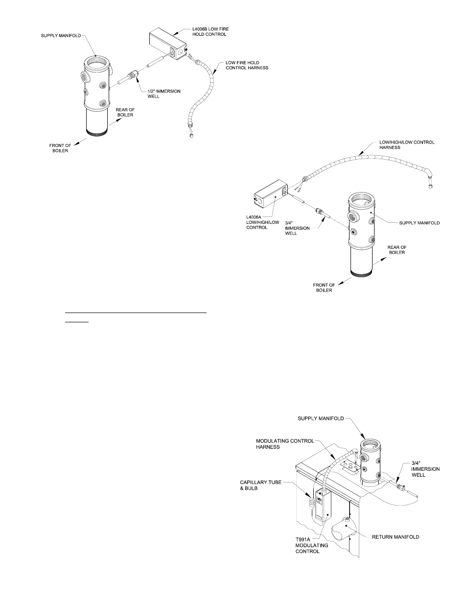
Figure : Install Low/High/Low Control
Figure 5: Install Modulation Control
Figure : Install Low Fire Hold Control
lg. hex head SMS per cover. Install 7/8”
knockout plugs (provided) to all unused
holes, refer to Figure 40.
b. Install
Modulating Control as follows:
i.
Apply thread sealant to 3/4” immersion
well and install in Tapping ‘H’ as shown in
Figure 38. Wrench well until water tight.
ii. Locate T991A Modulation control and
remove knockout on casing closest to
temperature control knob. Connect end
of harness with forked terminals to casing
knockout.
Connect wires to terminals as follows:
B Terminal - Black Wire w/White Tracer
W Terminal - Gray Wire
R Terminal - Red Wire w/White Tracer
iii. Install Remote Sensing Bulb into control
well and secure with retaining clip. Coil
excess sensor tubing as shown in Figure 45.
iv. Mount T991A Control to rear panel on
left side of return manifold with two (2)
self drilling #8 x 1/2” lg. hex head SMS
(provided) as shown in Figure 45.