Burnham MPC User Manual
Page 38
8
E.
Installing Internal Wiring Harness for Control/Safety
Circuits - refer to Figures 24a through 24g.
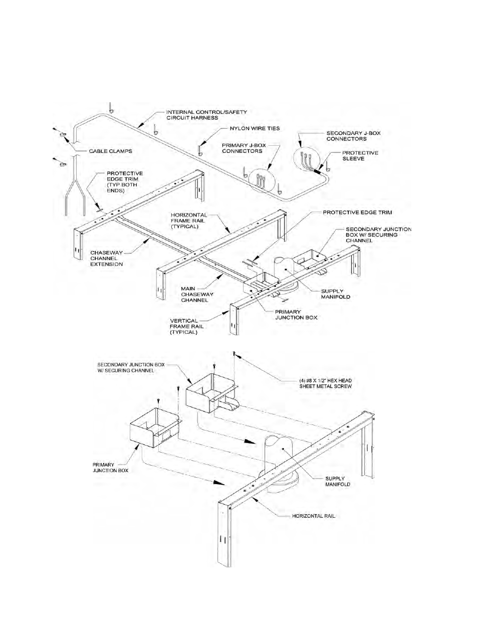
1. See Figure 24a for layout of Internal wiring harness
components.
2. Locate junction boxes shipped in Jacket Frame
Carton marked ‘JF’. As viewed from the rear,
install primary junction box (without extension
piece) to horizontal channel, on the left side of
supply manifold, using two (2) #8 x ½” lg. hex
head sheet metal screws, see Figure 24b. Install
secondary junction box with extension piece to
horizontal channel on right side of supply manifold
using two (2) #8 x ½” lg. sheet metal screws.
Figure a: Internal Wiring Harness Components
Figure b: Internal Wiring Harness Components - Mounting Junction Boxes
This manual is related to the following products: