Burnham MPC User Manual
Page 46
6
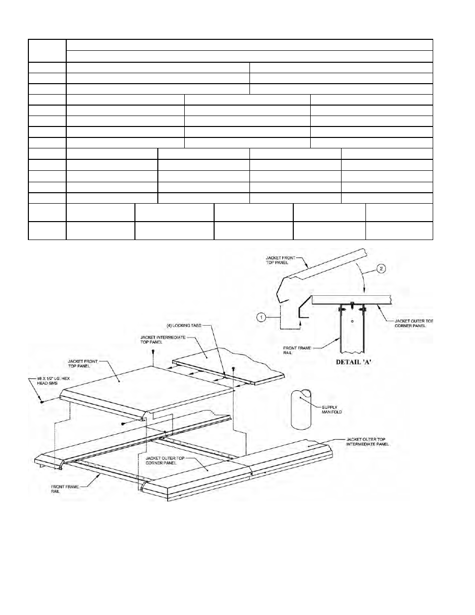
step 1. Position front panel at approximately 30°
angle, hook front flange under clips on outer top
corner panels as shown in Figure 30a, Detail A, Step
1. Lower rear of panel into position between outer
Boiler
Size
Order of Assembly
Front
f Block Assembly g Rear
4 Section
22-1/4” Front Top Panel
11-3/8” Rear Top Panel
5 Section
29” Front Top Panel
11-3/8” Rear Top Panel
6 Section
35¾” Front Top Panel
11-3/8” Rear Top Panel
7 Section
22-1/4” Front Top Panel
20-1/4” Intermediate Top Panel
11-3/8” Rear Top Panel
8 Section
22-1/4” Front Top Panel
27” Intermediate Top Panel
11-3/8” Rear Top Panel
9 Section
29” Front Top Panel
27” Intermediate Top Panel
11-3/8” Rear Top Panel
10 Section
29” Front Top Panel
33-3/4” Intermediate Top Panel
11-3/8” Rear Top Panel
11 Section
35-3/4” Front Top Panel
33-3/4” Intermediate Top Panel
11-3/8” Rear Top Panel
12 Section
29” Front Top Panel
27” Intermediate Top Panel
20-1/4” Intermediate Top Panel
11-3/8” Rear Top Panel
13 Section
29” Front Top Panel
27” Intermediate Top Panel
27” Intermediate Top Panel
11-3/8” Rear Top Panel
14 Section
35-3/4” Front Top Panel
27” Intermediate Top Panel
27” Intermediate Top Panel
11-3/8” Rear Top Panel
15 Section
29” Front Top Panel
33-3/4” Intermediate Top Panel
33-3/4” Intermediate Top Panel
11-3/8” Rear Top Panel
16 Section
35-3/4” Front Top Panel
33-3/4” Intermediate Top Panel
33-3/4” Intermediate Top Panel
11-3/8” Rear Top Panel
17 Section
29” Front Top Panel
27” Intermediate
Top Panel
27” Intermediate
Top Panel
27” Intermediate
Top Panel
11-3/8” Rear
Top Panel
18 Section
35-3/4” Front
Top Panel
27” Intermediate
Top Panel
27” Intermediate
Top Panel
27” Intermediate
Top Panel
11-3/8” Rear
Top Panel
Table XI: Jacket Top Panel Arrangement
Figure 0a: Installing Jacket Top Panels - Viewed From Front
top corner panel and secure front flange to clips
with two (2) #8 x ½” lg. hex head SMS as shown in
Figure 30a. Secure rear flange to outer top corner
panels with two (2) #8 x ½” lg. SMS as shown in
Figure 30b.