Burnham MPC User Manual
Page 54
5
s.
Installing Optional Controls (if applicable):
1. Install M&M 750P-MT-120 Probe Low Water Cut
Off (LWCO)
a. Apply thread sealant to ¾” probe and install in
Tapping ‘E’, see Figure 38. Wrench hex until
water tight.
b. Remove 2
nd
knockout from bottom of M&M
750P LWCO control case. Connect end
of harness with forked terminals to casing
knockout, see Figure 41. Connect wires to
terminal block as follows:
Terminal 1 - Black Wire w/ Red Tracer
Terminal 2 - Pink Wire
Terminal 3 - Red Wire w/ Black Tracer
Terminal 4 - Brown Wire
Terminal 5 - Violet Wire
c. Mount LWCO Control on probe and tighten
screws.
d. Connect ring terminal on black probe wire from
circuit board to terminal on probe and tighten
wing nut.
e. Connect opposite end of M&M 750P LWCO
control harness to left side junction box cover
‘B’, hole location #7 as shown in Figure 40.
(It may be necessary to clip the conduit
connector nut and flex it slightly to slide it over
the control harness connectors. Nut should still
be able to be tightened against cover plate.)
f. Locate mating connectors labeled “LWCO
Power” and “LWCO Contacts” inside left
junction box. Join mating connectors which
are polarized and lock together. Lightly tug on
connectors to make sure they are secure.
g. Proceed to next control option listed below for
installation details. If no other controls are being
installed at this time, secure cover ‘A’ and cover
‘B’ to jacket rear top panel with two (2) #8 x
1/2” lg. hex head SMS per cover.
Install 7/8” knockout plugs (provided) to all
unused holes, refer to Figure 40.
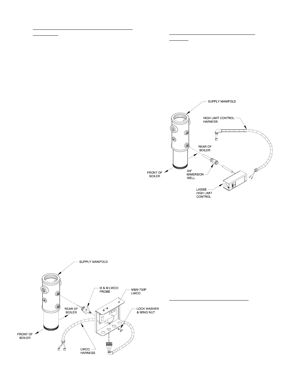
2. Install High Limit Control w/Manual Reset
(L4006E)
a. Apply thread sealant to 3/4” immersion well
and install in Tapping ‘F’ as shown in Figure 38.
Wrench well until water tight.
b. Locate L4006E High Limit Control and
remove knockout on casing closest to mounting
hole. Connect end of harness with forked
terminals to casing knockout. Connect orange
wires to terminals on limit control, wires are
interchangeable. Refer to Figure 42.
Figure 1: Install Probe Low Water Cut Off
Figure : Install High Limit Control
c. Connect opposite end of L4006E High Limit
Control harness to left side junction box cover
‘B’, hole location #5 as shown in Figure 40.
d. Locate mating connector labeled “Limit” inside
left junction box. Join mating connectors which
are polarized and lock together. Lightly tug on
connectors to make sure they are secure.
e. Proceed to next appropriate control option
listed below for installation details. If no other
controls are being installed at this time, secure
Cover ‘A’ and Cover ‘B’ to jacket rear top panel
with two (2) #8 x 1/2” lg. hex head SMS per
cover. Install 7/8” knockout plugs (provided) to
all unused holes, refer to Figure 40.
3. Install Low Fire Hold Control (L4006B)
a. Apply thread sealant to 1/2” immersion well
and install in Tapping ‘J’ as shown in Figure 38.
Wrench well until water tight.
b. Locate L4006B Low Fire Hold control and
remove knockout on casing closest to mounting
hole. Connect end of harness with forked
terminals to casing knockout. Connect blue
wires to terminals on limit control, wires are
interchangeable. Refer to Figure 43.