Input/output (i/o) port: connections and wiring, Ir/serial port: connections and wiring – AMX Signature Series NetLinx Integrated Controller NI-3101-SIG User Manual
Page 22
Connections and Wiring
12
NI-3101-SIG Signature Series NetLinx Integrated Controller
Input/Output (I/O) Port: Connections and Wiring
The I/O port responds to either switch closures or voltage level (high/low) changes, or it can be used for logic-
level outputs.
Up to eight devices may be connected to the I/O connectors on the NI-3101-SIG (FIG. 9). A contact closure
between the GND and an I/O port is detected as a Push.
When used for voltage inputs, the I/O port detects a low signal (0 - 1.5 VDC) as a Push, and a high
signal (3.5 - 5 VDC) as a Release (this IO port uses 5V logic but can handle up to 12V without
harm).
When used for outputs, the I/O port acts as a switch to GND and is rated for
200 mA @ 12 VDC. This device can use up to 8 I/O ports.
The PWR pin provides +12 VDC @ 200 mA and is designed as a power output for the PCS Power
Current Sensors, VSS2 Video Sync Sensors (or equivalent).
The GND connector is a common ground and is shared by all I/O ports. A common ground is
shared with I/O ports 1 - 8.
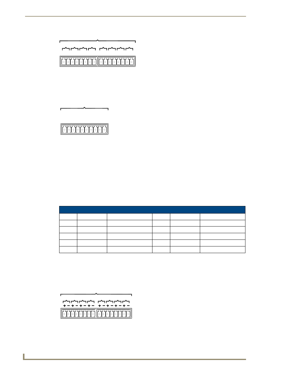
IR/Serial Port: Connections and Wiring
Up to eight IR- or Serial-controllable devices may be connected to the IR/Serial connectors on the rear of the
NI-3101 (FIG. 10). These connectors accept an IR Emitter (CC-NIRC) that mounts onto the device's IR
window, or a mini-plug (CC-NSER) that connects to the device's control jack. A data 0 - 5 VDC device may
also be connected. These units come with two CC-NIRC IR Emitters (FG10-000-11).
FIG. 8
RELAY connector (male) NI-3101-SIG
FIG. 9
INPUT/OUTPUT connector (male)
I/O Port Wiring Specifications - NI-3101-SIG
Pin
Signal
Function
Pin
Signal
Function
1
GND
Signal GND
6
I/O 5
Input/Output
2
I/O 1
Input/Output
7
I/O 6
Input/Output
3
I/O 2
Input/Output
8
I/O 7
Input/Output
4
I/O 3
Input/Output
9
I/O 8
Input/Output
5
I/O 4
Input/Output
10
12 VDC
PWR
FIG. 10
IR/SERIAL (male)
2
4
A
B
3
B
A
B
1
A
A B
RELAYS (Port 4)
RELAYS (Port 8)
B
6
A
8
B
B
B
7
A
5
B
A
A
4
B A
A
3
A
2
B
1
A
B
NI-3101-SIG relay connector
configuration (Port 8)
I / O (Port 17)
4
+12V
7
8
6 5
GN
D
2
3
1
I / O (Port 9)
4
+12V
2
3
1
GN
D
NI-3101-SIG I/O connector
configuration (Port 17)
IR / SERIAL (Ports 5-8)
IR / SERIAL (Ports 9-16)
8
7
6
4
5
3
2
1
4
2
3
1
NI-3101-SIG IR/Serial connector
configuration (Port 9-16)