Agilent Technologies 01664-97005 User Manual
Page 114
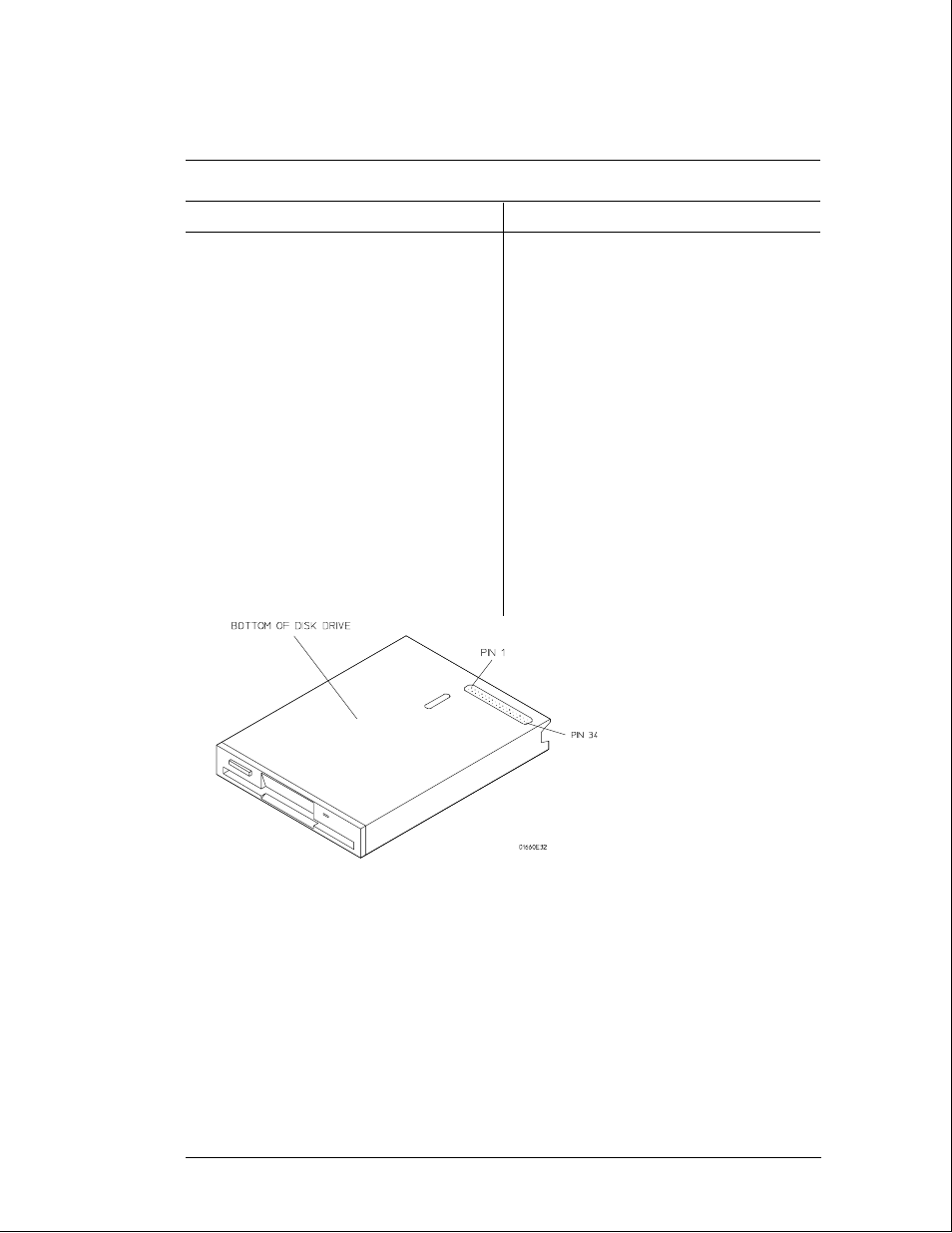
6
Check for the following voltages and signals using an oscilloscope.
Disk Drive Voltages
Pin
Signal Description
Pin
Signal Description
1
NC
2
Disk Change
3
NC
4
High Density
5
NC
6
NC
7
+5 V
8
Index
9
+5 V
10
Drive Select
11
+5 V
12
NC
13
Ground
14
NC
15
Ground
16
Motor On
17
Ground
18
Direction
19
Ground
20
Step
21
Ground
22
Write Data
23
Ground
24
Write Gate
25
Ground
26
Track 00
27
Ground
28
Write Protect
29
Ground
30
Read Data
31
Ground
32
Side Select
33
Ground
34
Ready
7
Select Stop, and turn off the logic analyzer. Remove the power cable.
8
Disconnect the disk drive cable and re-install the disk drive in the logic analyzer.
9
Reconnect the disk drive cable and install the cover on the logic analyzer.
Troubleshooting
To test the disk drive voltages
5–26