Filters, 6 filter sizing, 7 membrane dryers – Norgren Filter Contents User Manual
Page 5
Filters
Littleton, CO USA
Phone 303-794-2611
www.norgren.com
ALE-Filter
1.6
FILTER SIZING
Selecting the proper size of filter for any
application should be done by determining the
maximum allowable pressure drop which can
be caused by the filter. The pressure drop can
be determined by referring to flow curves
provided by the manufacturer.
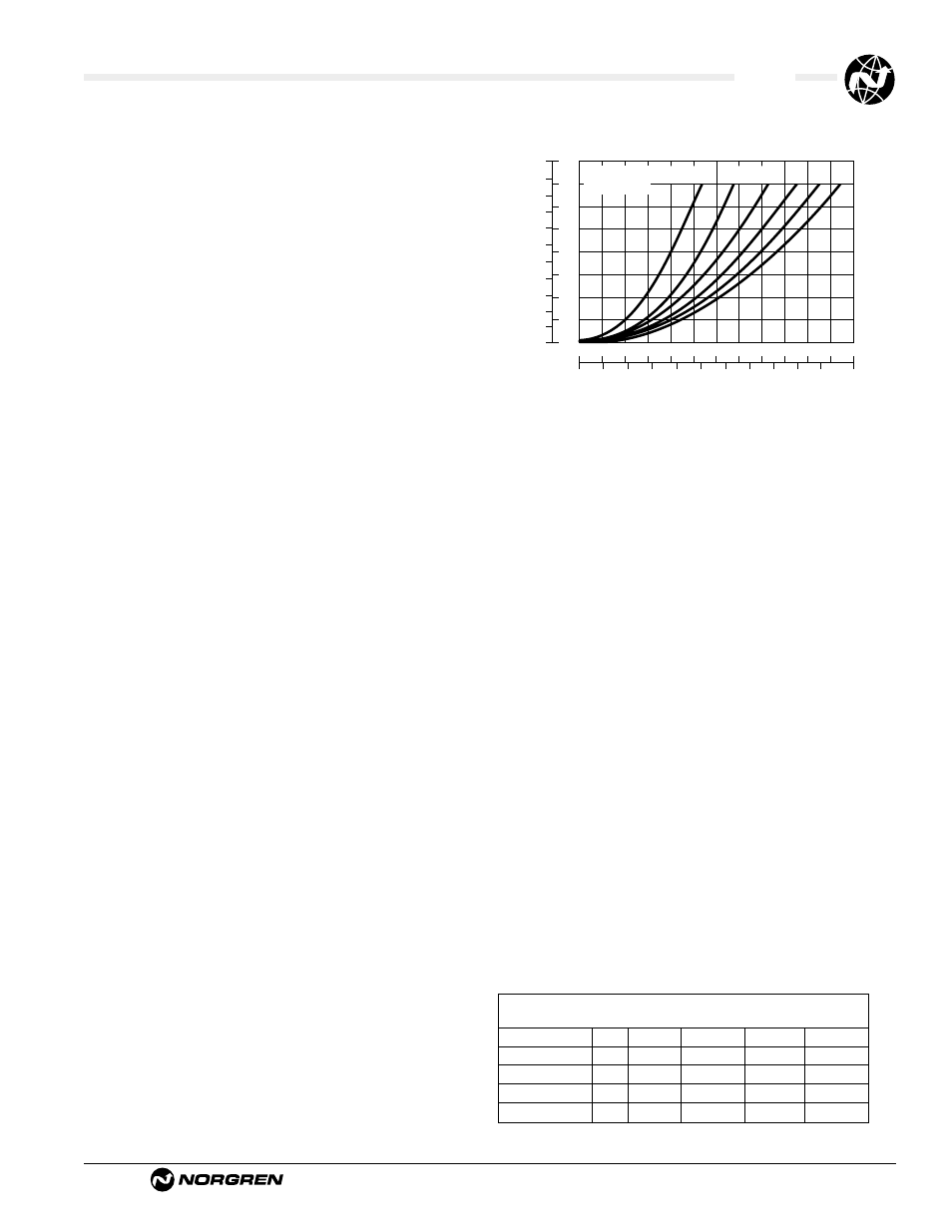
The flow characteristic curves should relate to
the fluid used, pressure, pipe port size and
micron rating of the filter element. Often the
parameters of pressure and flow are labeled in
metric and imperial units. The vertical axis is
the pressure drop across the filter, and the
horizontal axis is the air flow through the filter.
Each curved line represents the filter flow and
pressure drop characteristics for different
operating pressures.
Example Find the pressure drop across the
filter when operating at 90 psig (6.2 bar) and
when 50 scfm (24 dm
3
/s) is flowing through
the filter.
Answer Locate 50 scfm (24 dm
3
/s) on the
horizontal axis. Read up to the intersecting
point on the 90 psig (6.2 bar)operating curve.
The pressure drop (or
∆
p) is approximately .6
psid (.04bar) on the vertical axis on the left of
the graph. (See graph)
0
0
0
10
20
30
40
50
Air Flow
Flow Characteristics
60
70
80
90
100
20
40
60
80 100 120 140 160 180 200 220 scfm
dm 3/s
0
05
10
15
20
25
30
35
40
45
bar d
psid
1
2
3
4
5
6
7
Pressure Drop
180
(12.5)
150
(10.4)
120
(8.3)
90
(6.2
60
(4.1)
35
(2.4)
psig
(bar)
INLET
PRESSURE
1.7
MEMBRANE DRYERS
For those applications where a low-pressure
dewpoint and low installation/operational cost
are required, Norgren provides an Excelon®
Membrane Dryer. This new product can
provide dewpoint suppression up to 80°F
(26°C) below ambient temperature and is
available with nominal flows of 2, 5, 10, 20,
and 30 scfm.
The Membrane Dryer is a variable dew point
suppression device constructed of an anodized
aluminum body with end caps. Inside the
body are bundles of special hollow fibers
(membranes) which are semi-permeable.
Moisture-laden air enters the fibers and water
vapor permeates through the walls to the
outside of the fibers. Dry air exits the device
through the outlet port. A small percentage of
dry air is diverted across the outside of the
fibers to sweep away and vent water vapor to
atmosphere.
This device provides variable dew point
suppression inversely related to flow. Lower
flows through a unit will increase contact time
with the membrane fibers, resulting in greater
dew point suppression. Higher flows will
result in a decreased level of dew point
suppression. Additionally, dew point
suppression is directly related to operating
pressure. Increasing the pressure applied will
result in a greater level of dew point
suppression. Therefore, it is always
recommend placing regulators downstream of
a membrane dryer to ensure the highest
pressure possible through the membrane dryer.
Model
Port Outlet Inlet Purge Press.
Flow
Flow
Flow
Drop
W07M2ANNNA
1/4" 2 scfm
2.2 scfm 0.2 scfm
0.4 psid
W72M2ANNNB
1/4" 5 scfm
5.6 scfm 0.6 scfm 0.32 psid
W72M2ANNNC
1/4" 10 scfm 11.2 scfm 1.2 scfm 0.90 psid
W74M4ANNND
1/2" 20 scfm 22.2 scfm 2.2 scfm 0.65 psid
W74M4ANNNE
1/2" 30 scfm 33.4 scfm 3.4 scfm 1.35 psid
Typical Flows for Membrane Dryers