F74c/h oil removal (coalescing) filters, Ale-2-9, Technical data – Norgren Filter Contents User Manual
Page 33: Typical performance characteristics, Iso symbols
F74C/H Oil Removal (Coalescing) Filters
Littleton, CO USA
Phone 303-794-2611
www.norgren.com
ALE-2-9
All Dimensions in Inches (mm)
Technical Data
Fluid: Compressed air
Maximum pressure
Transparent bowl: 150 psig (10 bar)
Metal bowl: 250 psig (17 bar)
Operating temperature*
Transparent bowl: -30° to 125°F (-34° to 50°C)
Metal bowl: -30° to 150°F (-34° to 65°C)
* Air supply must be dry enough to avoid ice formation at temperatures below 35°F (2°C).
Particle removal: Down to 0.01 µm
Air quality: Within ISO 8573-1, Class 1 (particulates) and Class 2 (oil content)
Maximum remaining oil content in outlet air: 0.01 ppm at 70°F (20°C) with an inlet
concentration of 17 ppm
Maximum flow at 90 psig (6.3 bar) inlet pressure to maintain stated oil removal
performance
F74C: 33.9 scfm (16 dm
3
/s)
F74H: 59.3 scfm (28 dm
3
/s)
Manual drain connection: Will fit 1/8-27 and 1/8-28 pipe thread.
Automatic drain connection: Will fit 1/8-27 and 1/8-28 pipe thread. - Flexible tube
with 3/16" (5mm) minimum I.D. can be connected to the automatic drain. Drain
may fail to operate if the tube I.D. is less than 3/16" (5mm). Avoid restrictions in
the tube.
Automatic drain operating conditions (float operated)
Bowl pressure required to close drain: Greater than 5 psig (0.3 bar)
Bowl pressure required to open drain: Less than 3 psig (0.2 bar)
Minimum air flow required to close drain: 2 scfm (1 dm
3
/s)
Manual operation: Depress pin inside drain outlet to drain bowl
Nominal bowl size: 7 fluid ounce (0.2 liter)
Materials
Body: Aluminum
Bowl
Transparent: Polycarbonate with steel bowl guard
Metal: Aluminum
Metal bowl liquid level indicator lens: Transparent nylon
Element: Synthetic fiber and polyurethane foam
Elastomers: Neoprene and Nitrile
Service indicator
Body: Transparent nylon
Internal parts: Acetal
Spring: Stainless steel
Elastomers: Nitrile
An automatic drain is a two-way valve, which will close when the system is
pressurized. The drain opens when the float rises due to accumulated liquid
and on depressurization.
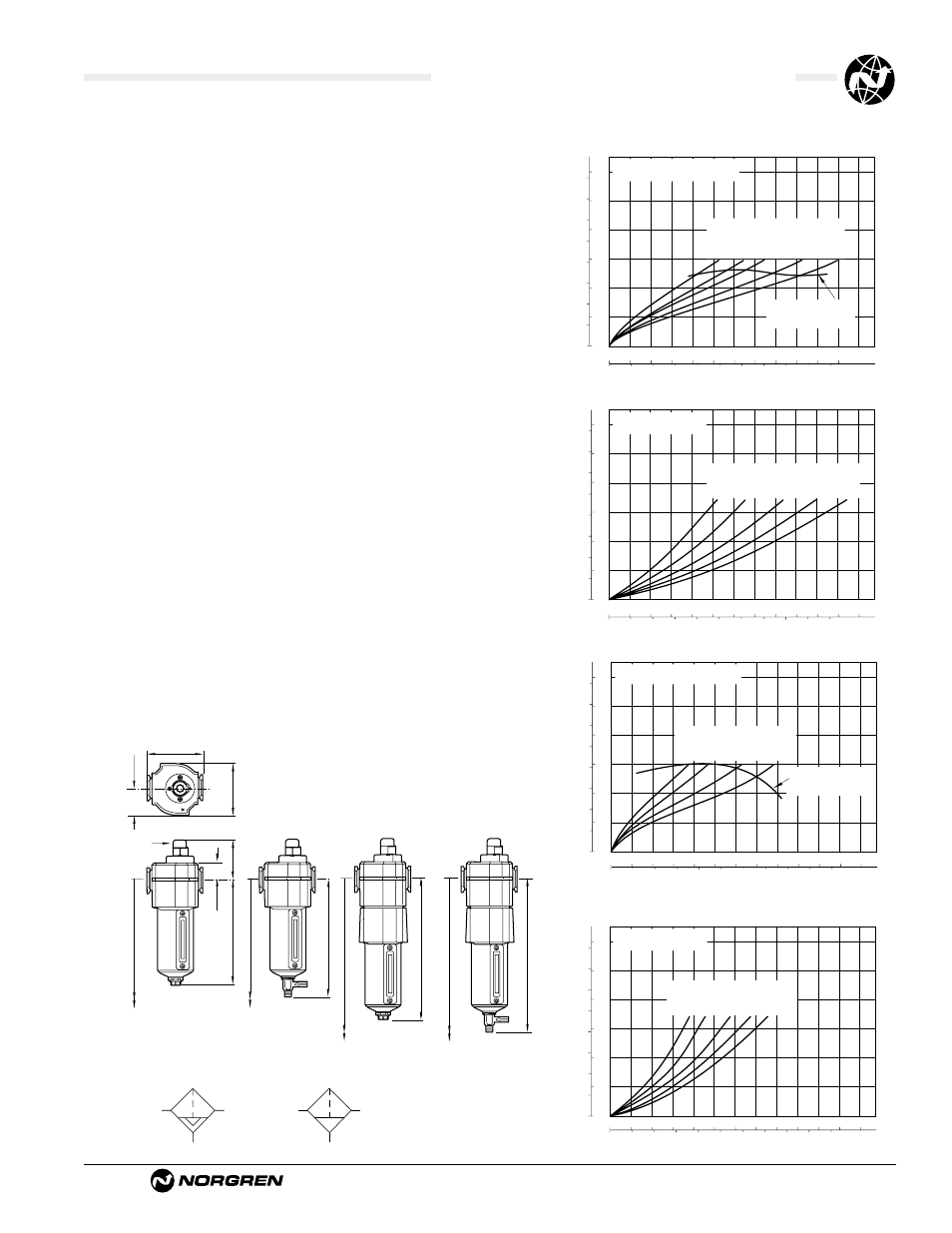
Typical Performance Characteristics
0 5 10 15 20 25
dm
3
/s
AIR FLOW
0 10 20 30 40 50 scfm
0.6
0.4
0.2
0
PRESSURE DROP
bar d
10
8
6
4
2
0
psid
PORT SIZE: 1/2"
ELEMENT: SATURATED (F74C)
36
(2.5)
90
(6.3)
58
(4.0)
150
(10.0)
116
(8.0)
INLET PRESSURE: psig (bar g)
FLOW CHARACTERISTICS
Maximum flow to
maintain stated oil
removal performance
PRESSURE DROP
0.6
0.4
0.2
0
bar d
10
8
6
4
2
0
psid
PORT SIZE: 1/2"
ELEMENT: DRY (F74C)
36
(2.5)
58
(4.0)
150
(10.0)
90
(6.3)
116
(8.0)
INLET PRESSURE: psig (bar g)
AIR FLOW
0 10 20 30 40 50
dm
3
/s
0 20 40 60 80 100
scfm
FLOW CHARACTERISTICS
F74C
PRESSURE DROP
0.6
0.4
0.2
0
bar d
10
8
6
4
2
0
psid
PORT SIZE: 1/2"
ELEMENT: SATURATED (F74H)
36
(2.5)
58
(4.0)
90
(6.3)
116
(8.0)
INLET PRESSURE: psig (bar g)
AIR FLOW
0 10 20 30 40 50
dm
3
/s
0 20 40 60 80 100 scfm
FLOW CHARACTERISTICS
Maximum flow to
maintain stated oil
removal performance
PRESSURE DROP
0.6
0.4
0.2
0
bar d
10
8
6
4
2
0
psid
PORT SIZE: 1/2"
ELEMENT: DRY (F74H)
36
(2.5)
58
(4.0)
150
(10.0)
90
(6.3)
116
(8.0)
INLET PRESSURE: psig (bar g)
0 20 40 60 80 100
dm
3
/s
AIR FLOW
0 40 80 120
160
200 scfm
FLOW CHARACTERISTICS
8.44 (215)
F74H, Automatic Drain
9.04 (230)
11.18 (284) **
11.81 (300)**
F74H, 1/4
Turn Manual Drain
6.95 (177)
F74C, 1/4
Turn Manual Drain
9.80 (249) **
3.15 (80)
1.45 (37)
2.89 (74)
2.36 (60)
†
1.00 (25)
Service
Indicator
6.35 (161)
F74C, Automatic Drain
9.17 (233) **
** Minimum clearance required to remove bowl.
† Dimension for alternative electrical service indicator is 1.98" (50.4 mm)
Automatic and Semi Automatic Drain
Manual Drain
ISO Symbols