F72c oil removal (coalescing) filters, Ale-2-5, Service kits – Norgren Filter Contents User Manual
Page 29: Technical data, Typical performance characteristics
F72C Oil Removal (Coalescing) Filters
Littleton, CO USA
Phone 303-794-2611
www.norgren.com
ALE-2-5
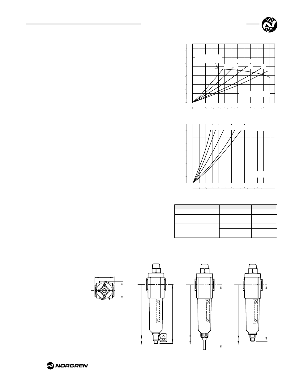
PORT SIZE: 1/4"
SATURATED ELEMENT
INLET PRESSURE: psig (bar)
FLOW CHARACTERISTICS
0 1 2 3 4 5
dm
3
/s
AIR FLOW
0 2 4 6 8 10 scfm
0.4
0.3
0.2
0.1
0
PRESSURE DROP
bar d
5
4
3
2
1
0
psid
36
(2.5)
23
(1.6)
58
(4.0)
91
(6.3)
116
(8.0)
Maximum flow to
maintain stated oil
removal performance
1.97 (50)
1.89 (48)
Bowl with
Automatic Drain
5.51 (140)
7.52 (191)
†
Bowl with
Semi auto Drain
7.48 (190)
9.84 (250)
†
Bowl with
1/4 Turn Manual Drain
5.83 (148)
7.83 (199)
†
(Top)
†
Minimum clearance required to remove bowl.
Service Kits
Item
Type
Part Number
Service kit
Seal and gasket
4380-500
Element
Coalescing
5925-09
Liquid level lens kit
Prismatic
4380-030
1/4 turn manual
619-50
Replacement drains
Semi automatic
5379-RK
Automatic 4000-50R
Service kit includes bowl o-rings.
Technical Data
Fluid: Compressed air
Maximum pressure:
Transparent bowl: Manual or semi automatic drain: 150 psig (10 bar)
Automatic drain: 116 psig (8 bar)
Metal bowl: Manual or semi automatic drain: 250 psig (17 bar)
Automatic drain: 116 psig (8 bar)
Operating temperature*: Transparent bowl: -30° to 125°F (-34° to 50°C)
Metal bowl: -30° to 150°F (-34° to 65°C)
* Air supply must be dry enough to avoid ice formation at temperatures below 35°F (2°C).
Particle removal: 0.01 µm
Air quality: Within ISO 8573-1, Class 1 (particulates) and Class 2 (oil content)
Maximum remaining oil content in outlet air:
0.01 ppm at 70°F (21°C) with an inlet concentration of 17 ppm.
Maximum flow with 90 psig (6.3 bar) inlet pressure**: 9.5 scfm (4.5 dm
3
/s)
** Maximum flow to maintain stated oil removal performance.
Manual drain connection: Will fit 1/8-27 and 1/8-28 pipe thread.
Semi automatic drain connection: Push on 5/16" (8 mm) ID tube
Semi automatic drain operating conditions (pressure operated):
Bowl pressure required to close drain: Greater than 1.5 psig (0.1 bar)
Bowl pressure required to open drain: Less than 1.5 psig (0.1 bar)
Minimum air flow required to close drain: 1 scfm (0.5 dm
3
/s)
Manual operation: Lift stem to drain bowl
Automatic drain connection: Will fit 1/8-27 and 1/8-28 pipe thread. - Flexible tube
with 3/16" (5mm) minimum I.D. can be connected to the automatic drain. Drain
may fail to operate if the tube I.D. is less than 3/16" (5mm). Avoid restrictions in
the tube.
Automatic drain operating conditions (float operated):
Bowl pressure required to close drain: Greater than 5 psig (0.3 bar)
Bowl pressure required to open drain: Less than 3 psig (0.2 bar)
Minimum air flow required to close drain: 0.2 scfm (0.1 dm
3
/s)
Manual operation: Depress pin inside drain outlet to drain bowl
Nominal bowl size
Long bowl: 2.2 fluid ounce (65 ml)
Materials
Body: Zinc
Bowl
Transparent: Polycarbonate
Guard for transparent bowl: Zinc
Metal: Zinc
Metal bowl liquid level indicator lens: Transparent nylon
Element: Synthetic fiber and polyurethane foam
Elastomers: Neoprene and nitrile
Service life indicator
Body: transparent nylon.
Internal parts: acetal.
Spring: stainless steel.
Elastomers nitrile
An automatic drain is a two-way valve, which will close when the system is
pressurized. The drain opens when the float rises due to accumulated liquid
and on depressurization.
PORT SIZE: 1/4"
DRY ELEMENT
INLET PRESSURE:
psig (bar)
FLOW CHARACTERISTICS
0 4 8 12 16 20
dm
3
/s
0 8 16 24 32 40 scfm
0.4
0.3
0.2
0.1
0
PRESSURE DROP
bar d
5
4
3
2
1
0
psid
36
(2.5)
23
(1.6)
58
(4.0)
91
(6.3)
116
(8.0)
Typical Performance Characteristics
All Dimensions in Inches (mm)