3 characteristics and specifications, Table 3-1. recommended operating conditions, Table 3-2. absolute maximum ratings – Cirrus Logic CS35L32 User Manual
Page 8: Table 3-3. dc characteristics, Table 3-2, Table 3-3, Table 3-1, Cs35l32
8
DS963F4
CS35L32
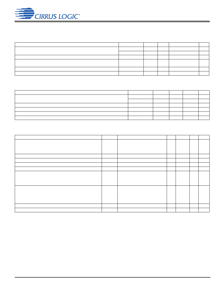
3 Characteristics and Specifications
3 Characteristics and Specifications
Table 3-1. Recommended Operating Conditions
GNDA = GNDP = 0 V, all voltages with respect to ground. Device functional operation is guaranteed within these limits. Functionality is not guaranteed
or implied outside of these limits. Operation outside of these limits may adversely affect device reliability.
Parameters Test
Conditions Symbol
Min
Max
Units
DC power supply
Analog (and digital I/O and core)
—
VA
1.71
1.89
V
Battery
—
VP
3.0
5.25
V
External voltage applied to analog inputs powered by VA (IREF+, FILT+)
1
1.The maximum overvoltage/undervoltage is limited by the input current.
—
V
INAS
–0.3
VA + 0.3
V
External voltage applied to analog inputs powered by SPKRSUPPLY (IN+,
IN–, ISENSE+, ISENSE–,VSENSE+, VSENSE–)
—
V
INSS
–0.3
SPKRSUPPLY + 0.3
V
External voltage applied to digital inputs
—
V
INDI
–0.3
VA + 0.3
V
Ambient temperature
—
TA
–10
+70
°C
Table 3-2. Absolute Maximum Ratings
GNDA = GNDP = 0 V; all voltages with respect to ground. Operation at or beyond these limits may permanently damage the device.
Parameters Test
Conditions Symbol
Min
Max
Units
DC power supply
Analog
—
VA
–0.3
2.22
V
Battery
—
VP
–0.3
6.0
V
Input current
1
1.
Any pin except supplies. Transient currents of up to ±100 mA on the analog input pins do not cause SCR latch up.
—
I
IN
—
±10
mA
Ambient operating temperature (local to device, power applied)
—
T
A
–40
+115
°C
Junction operating temperature (power applied)
—
T
J
–40
+150
°C
Storage temperature
—
T
STG
–65
+150
°C
Table 3-3. DC Characteristics
Test conditions, except where noted otherwise: VA = 1.8 V, VP = 3.6 V, VBST = 5.0 V, GNDA = GNDP = 0 V, TA = +25°C
.
Parameters
Symbol Test
Conditions
Min
Typical Max Units
Differential Input resistance (IN+ to IN–)
R
INDIF
Amp gain = 9 dB
Amp gain = 12 dB
Amp gain = 15 dB
Amp gain = 18 dB
—
—
—
—
63
51
40
31
—
—
—
—
k
k
k
k
FILT+ voltage
—
—
—
VA
—
—
Overtemperature shutdown threshold
T
OP
—
—
150
—
°C
Overtemperature warning threshold
T
WRN
—
—
135
—
°C
Overtemperature warning threshold deviation
—
—
—
±10
—
°C
Low battery threshold
—
LOWBAT_TH = 00
LOWBAT_TH = 01
LOWBAT_TH = 10
LOWBAT_TH = 11
—
—
—
—
3.10
3.20
3.30
3.40
—
—
—
—
V
V
V
V
Low-battery recovery threshold
—
LOWBAT_RECOV = 001
LOWBAT_RECOV = 010
LOWBAT_RECOV = 011
LOWBAT_RECOV = 100
LOWBAT_RECOV = 101–11x
—
—
—
—
—
3.20
3.30
3.40
3.50
3.60
—
—
—
—
—
V
V
V
V
V
VP undervoltage lockout threshold (VP falling)
UVLO
—
—
2
—
V
VP undervoltage lockout hysteresis
—
—
—
100
—
mV