Table 3-9. psrr characteristics, Table 3-10. power consumption, Cs35l32 – Cirrus Logic CS35L32 User Manual
Page 12
12
DS963F4
CS35L32
3 Characteristics and Specifications
Table 3-9. PSRR Characteristics
Test conditions, except where noted otherwise: VA = 1.8 V, VP = 3.6 V, VBST = VP, amp gain = 12 dB, GNDA = GNDP = 0 V, T
A
= +25°C.
Parameters
Conditions
Noise
Injected Into
Noise
Measured On
Noise
Amplitude (mV)
Noise
Frequency (Hz)
Min
Typical
Max
Units
Speaker amplifier
PSRR
VBST = VP
VA
SPKOUT±
100
217
1k
20k
—
—
—
75
75
70
—
—
—
dB
dB
dB
VP
SPKOUT±
100
217
1k
20k
—
—
—
70
70
55
—
—
—
dB
dB
dB
VPMON PSRR
VBST = VP
VA
SDOUT
100
217
1k
20k
—
—
—
36
36
33
—
—
—
dB
dB
dB
VSENSE± PSRR
1
1.The speaker voltage monitor has a lower PSRR because its input path has an attenuation of 16.6 dB. The PSRR specification is referred to the input
signal and, as such, includes the loss of 16.6 dB.
VBST = VP
VA
SDOUT
100
217
1k
20k
—
—
—
60
60
50
—
—
—
dB
dB
dB
ISENSE± PSRR
VBST = VP
VA
SDOUT
100
217
1k
20k
—
—
—
60
60
60
—
—
—
dB
dB
dB
Table 3-10. Power Consumption
Test conditions, except where noted otherwise: VA = 1.8 V, VP = 3.6 V, VBST = VP, GNDA = GNDP = 0 V, T
A
= +25°C.
Use Configuration
Typical Current
i
VP
i
VA
Units
Powered up
(
PDN_BST = 00)
RESET asserted, MCLK, SCLK, LRCK inactive
1
1
A
IN+ IN–
shorted to ground, LEDs off, monitors powered down
1
1.Refer to
for configuring monitor power down
No C
OUT
3270
390
A
IN+ IN–
shorted to ground, LEDs off, monitors powered down
C
OUT
= 470 pF (See
4275
390
A
IN+ IN–
shorted to ground, LEDs off, monitors powered up
No C
OUT
3360
1435
A
IN+ IN–
shorted to ground, LEDs off, monitors powered up
C
OUT
= 470 pF See
4360
1435
A
Boost Mode
bypass
(
PDN_BST = 01)
.
RESET asserted, MCLK, SCLK, LRCK inactive
1
1
A
IN+ IN–
shorted to ground, LEDs off, monitors powered down
No C
OUT
1983
390
A
IN+ IN–
shorted to ground, LEDs off, monitors powered down
C
OUT
= 470 pF (See
3093
390
A
IN+ IN–
shorted to ground, LEDs off, monitors powered up
No C
OUT
2074
1435
A
IN+ IN–
shorted to ground, LEDs off, monitors powered up
C
OUT
= 470 pF See
3185
1435
A
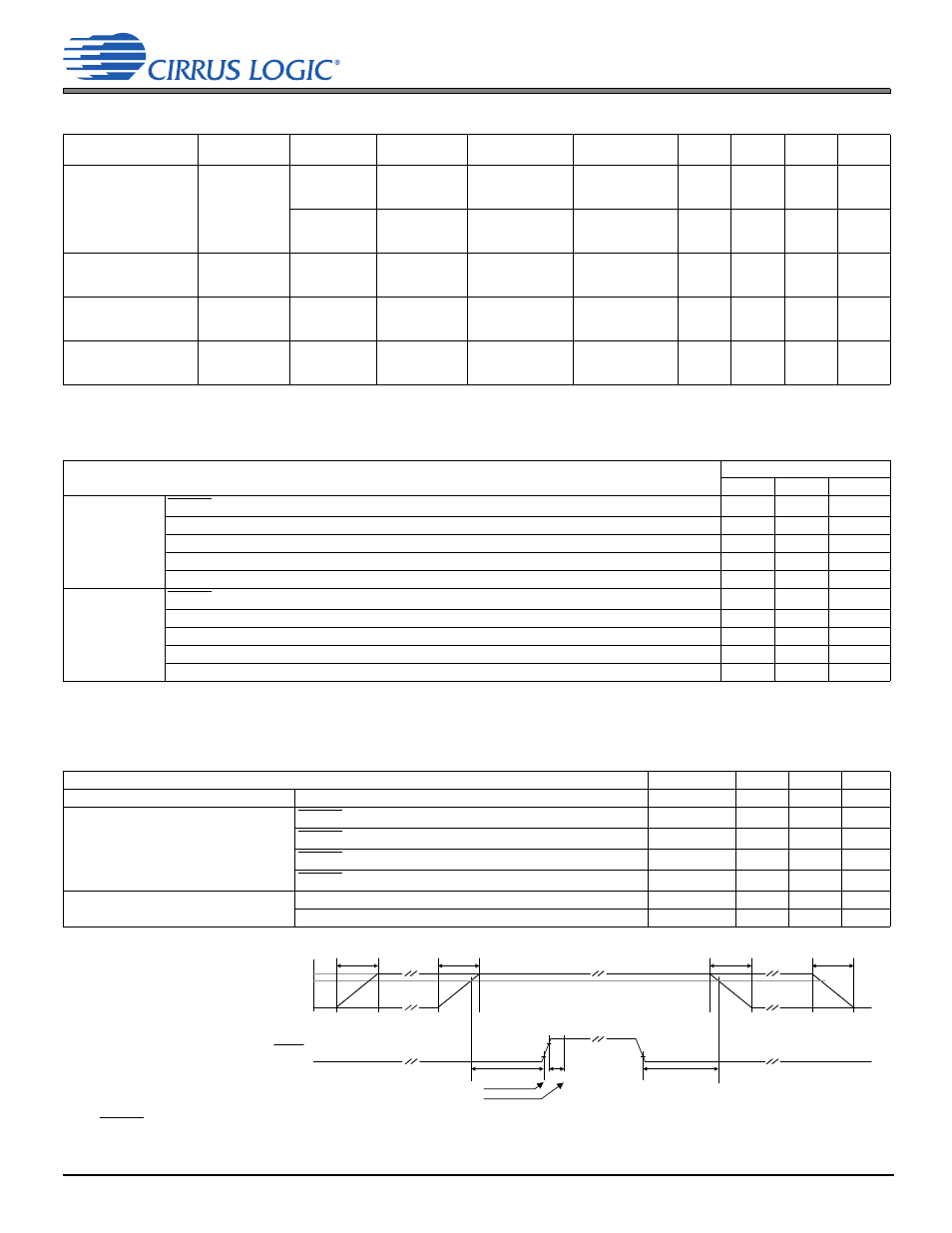
Table 3-11. Switching Specifications: Power, Reset, Master Clocks
Test conditions, except where noted otherwise: VA = 1.8 V, VP = 3.6 V, VBST = 5.0 V, T
A
= +25°C, GNDA = GNDP = 0 V.
shows typical
connections; GNDA = GNDP = 0 V.
describes some parameters in detail; input timings are measured at V
IL
and V
IH
thresholds; output timings
are measured at V
OL
and V
OH
thresholds (see
).
Parameters
Symbol
1
1.Power and reset sequencing
Min Max
Units
Power supplies
2
2.VP supply may be applied or removed independently of RESET and the other power rails. See
for additional details.
Power supply ramp up/down
t
PWR-RUD
—
100
ms
RESET low (logic 0) pulse width
t
RLPW
1
—
ms
RESET hold time after power supplies ramp up
t
RH(PWR-RH)
1
—
ms
RESET setup time before power supplies ramp down
t
RS(RL-PWR)
1
—
ms
RESET rising edge to control-port active
t
IRS
[3]
3.The
RESET
rising-edge-to-control-port-active timing, t
irs
, is specified in
.
—
ns
Master clocks
MCLK frequency
4
4.Maximum frequency for highest supported nominal rate is indicated. The supported nominal serial port sample rates are found in
.
f
MCLK
—
12.3
MHz
MCLK duty cycle
D
MCLK
45
55
%
V
MIN
GND
Internal supplies stable
V
OPERATING
t
RH(PWR-RH)
t
IRS
Control port active
t
RS(RL-PWR)
RESET
t
PWR-RUD
t
PWR-RUD
t
PWR-
RUD
t
PWR-RUD
1
st
Supply
Up
Last
Supply
Up
1
st
Supply
Down
Last
Supply
Down