2 typical connection diagram, 7 regi, Cs35l32 – Cirrus Logic CS35L32 User Manual
Page 7: Applications processor
DS963F4
7
CS35L32
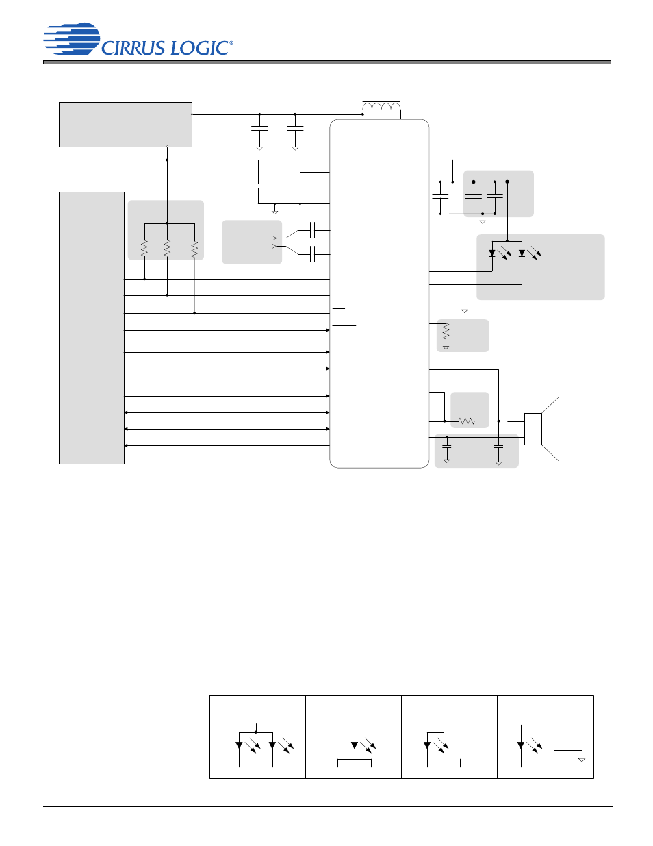
2 Typical Connection Diagram
2 Typical Connection Diagram
Figure 2-1. Typical Connection Diagram
Battery
1
H
C
OUT
0.1
0.1
F
**
L
BST
44.2 k
R
BST_SNS
8
C
OUT
**
Applications
Processor
0.1
F
10
F
C
BST
*
*
R
P
R
P
R
P
_
I
PMU
10
F
*
0.1
F
VA
*
4.7
F
*
Line Input 1
CS35L32
ISENSE–/
VSENSE+
SPKOUT+
ISENSE+
IREF+
SPKOUT–/
VSENSE–
VBST
GNDP
FLOUT1
FLOUT2 / AD0
GNDPLED
SPKRSUPPLY
SDOUT
LRCK
SCLK
MCLK
FLEN
FLINH
SCL
SDA
INT
RESET
VA
FILT+
GNDA
IN+
IN–
VP
SW
*
*
3.0–5.25 V
1.71–1.89 V
10
F
Notes:
• All external passive component values are nominal values.
Key for capacitor types required:
* Use low ESR, X7R/X5R capacitors.
** Use low ESR, X7R capacitors.
If no type symbol is shown next to a capacitor, any type may be used.
• As required, add protection circuitry to ensure compliance with the absolute maximum ratings in
.
1. C
BST
is a ceramic capacitor and derates at DC voltages higher than 0 V. In this application, the capacitor should not derate to a value lower
than 4
F across the specified boost output voltage in
. Capacitor tolerance and the temperature coefficient should also be taken
into account to guarantee the 4-
F value.
2. Minimum pull-up resistor values are selected in accordance with the
OL
specification
. Maximum pull-up resistances are selected
based on load capacitance and relevant switching specs (
3. Select each capacitor to be 0.22
F for an 18-Hz passband @ 12-dB amplifier gain, for a 3-dB roll-off. The equation for calculating the
capacitance for a given passband is C = 1/(
* f * R
INDIF
), where C is in F, R
INDIF
is the differential input resistance in
and f is in Hz (see
the differential input resistance specification in
). Signals IN+ and IN– are subject to the recommended ranges in
.
4. R
BST_SNS
is inherently tied to the accuracy of the BST_IPK current limit. A resistor with a 0.1% tolerance is required for this component to
meet the specified IMAX(B) max and min values in
.
5. The required tolerance on the 0.1-
ISENSE resistor is 1%. The required temperature coefficient is ±200 ppm/°C.
6. C
OUT
capacitors are optional EMI suppressors used with CS35L32 edge-rate control, depending on application requirements. Because
switching losses increase linearly with increases to these capacitances, it is recommended that C
OUT
values not exceed 2 nF. The
recommended value is 470 pF.
7. LED and I
2
C addressing options:
VBST
VBST
c) AD0 = 1
d) AD0 = 0
b) AD0 = 1
a) AD0 = 1
VBST
VBST
FLOUT1 FLOUT2
FLOUT1 FLOUT2
FLOUT1 FLOUT2
FLOUT1 FLOUT2
NC
See Note 7 for LED
and I
2
C addressing
options.
Note 1
Note 2
Note 5
Note 4
Note 6