Table 3-13, Ecified in, Cs35l32 – Cirrus Logic CS35L32 User Manual
Page 14
14
DS963F4
CS35L32
3 Characteristics and Specifications
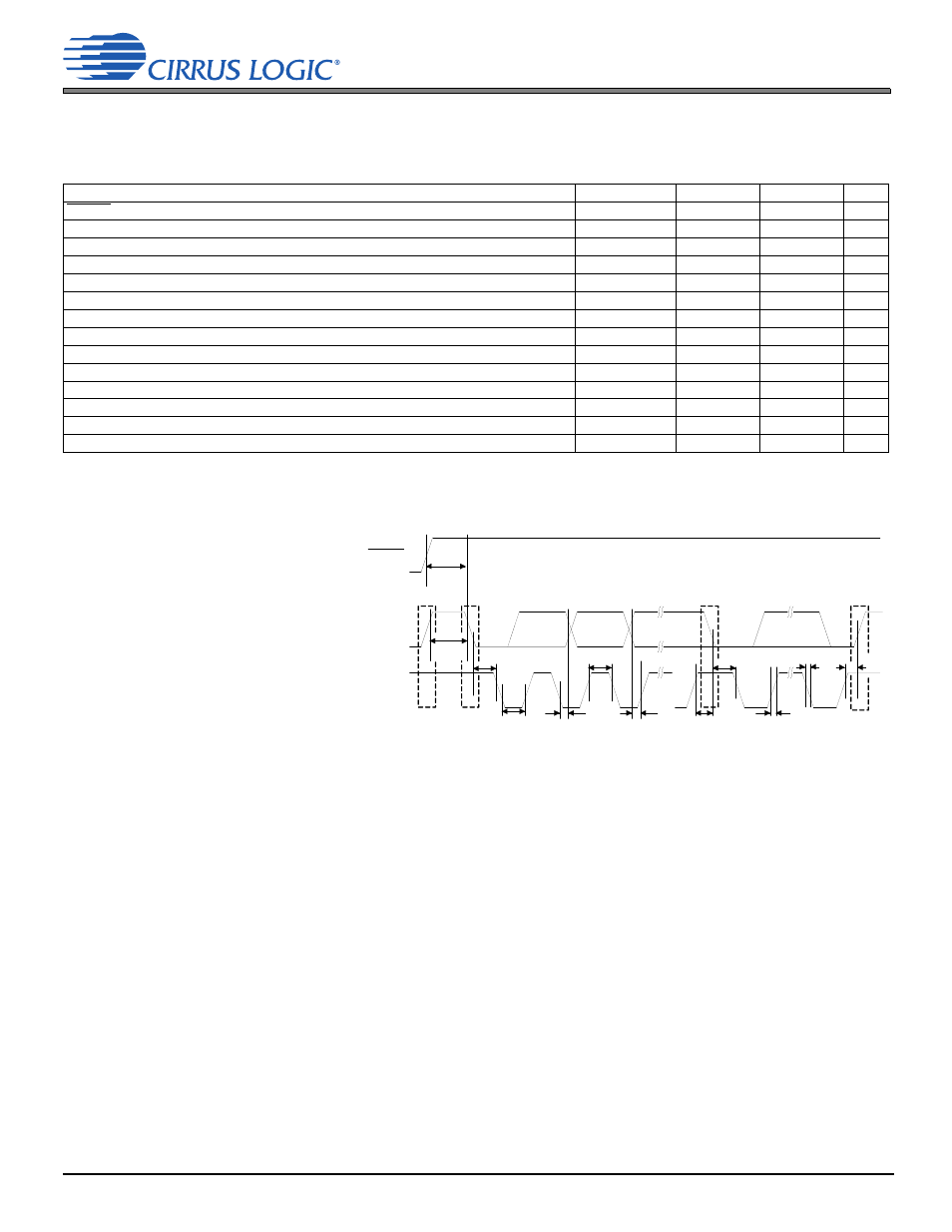
Table 3-13. Switching Specifications: I²C Control Port
Test conditions, except where noted otherwise: VA = 1.8 V, VP = 3.6 V, VBST = 5.0 V, T
A
= +25°C, Inputs: Logic 0 = GNDA = GNDP = 0 V, Logic 1 =
VA; SDA load capacitance equal to maximum value of C
B
specified below; minimum SDA pull-up resistance, R
P(min)
.
1
describes some
parameters in detail. All specifications are valid for the signals at the pins of the CS35L32 with the specified load capacitance; input timings are measured
at V
IL
and V
IH
thresholds; output timings are measured at V
OL
and V
OH
1.The minimum R
P
and R
P_I
values (resistors shown in
) are determined using the maximum level of VA, the minimum sink current strength of
their respective output, and the maximum low-level output voltage V
OL
(specified in
P
and R
P_I
values may be determined
by how fast their associated signals must transition (e.g., the lower the value of R
P
, the faster the I
2
C bus is able to operate for a given bus load
capacitance). See the I²C switching specifications in
and the I²C bus specification referenced in
.
Parameter
Symbol
2
2.I²C control-port timing.
Min
Max
Units
RESET rising edge to start
t
IRS
500
—
ns
SCL clock frequency
f
SCL
—
400
kHz
Start condition hold time (before first clock pulse)
t
HDST
0.6
—
µs
Clock low time
t
LOW
1.3
—
µs
Clock high time
t
HIGH
0.6
—
µs
Setup time for repeated start condition
t
SUST
0.6
—
µs
SDA input hold time from SCL falling
3
3.Data must be held long enough to bridge the transition time, t
F
, of SCL.
t
HDDI
0
0.9
µs
SDA output hold time from SCL falling
t
HDDO
0.2
0.9
µs
SDA setup time to SCL rising
t
SUD
100
—
ns
Rise time of SCL and SDA
t
RC
—
300
ns
Fall time of SCL and SDA
t
FC
—
300
ns
Setup time for stop condition
t
SUSP
0.6
—
µs
Bus free time between transmissions
t
BUF
1.3
—
µs
SDA bus capacitance
C
B
—
400
pF
t
BUF
t
LOW
Stop
Start
Start
Stop
Repeated
SDA
SCL
t
IRS
RESET
t
HDDI,
t
HDDO
t
SUD
t
SUST
t
RC
t
HDST
t
HIGH
t
HDST
t
FC
t
SUSP