1 error conditions, 8 signal monitoring, 1 power-up and power-down bits (pdn_xmon) – Cirrus Logic CS35L32 User Manual
Page 19: Section 4.8, Signal monitoring, Section 4.7.1, Cs35l32
DS963F4
19
CS35L32
4.8 Signal Monitoring
4.7.1
Error Conditions
lists overtemperature error status and mask bits.
The overtemperature error and warning error conditions are described in detail in the following:
• Overtemperature warning (OTW). An OTW event occurs when the die temperature exceeds the overtemperature
threshold (listed in
). When this occurs, an
(see
) event is registered in the interrupt status
(
); if M_OTW = 0, INT is asserted.
To exit the condition, the temperature must drop below the threshold and interrupt status 1 register must be read.
• Overtemperature error (OTE). An OTE event occurs when the die temperature exceeds the internally preset error
threshold (see
) event is registered in the interrupt status and, if
= 0, INT is asserted. The CS35L32 shuts down, the Class D amplifier enters Speaker Safe Mode, as
described in
, and the LED drivers shut down.
To exit, the temperature must drop below the overtemperature shutdown threshold and
must be
sequenced as described in
. After OTE release, the amplifier and LED drivers recover to preshutdown
settings. The LED drivers must be retriggered with FLEN and/or FLINH inputs for a lighting event to occur.
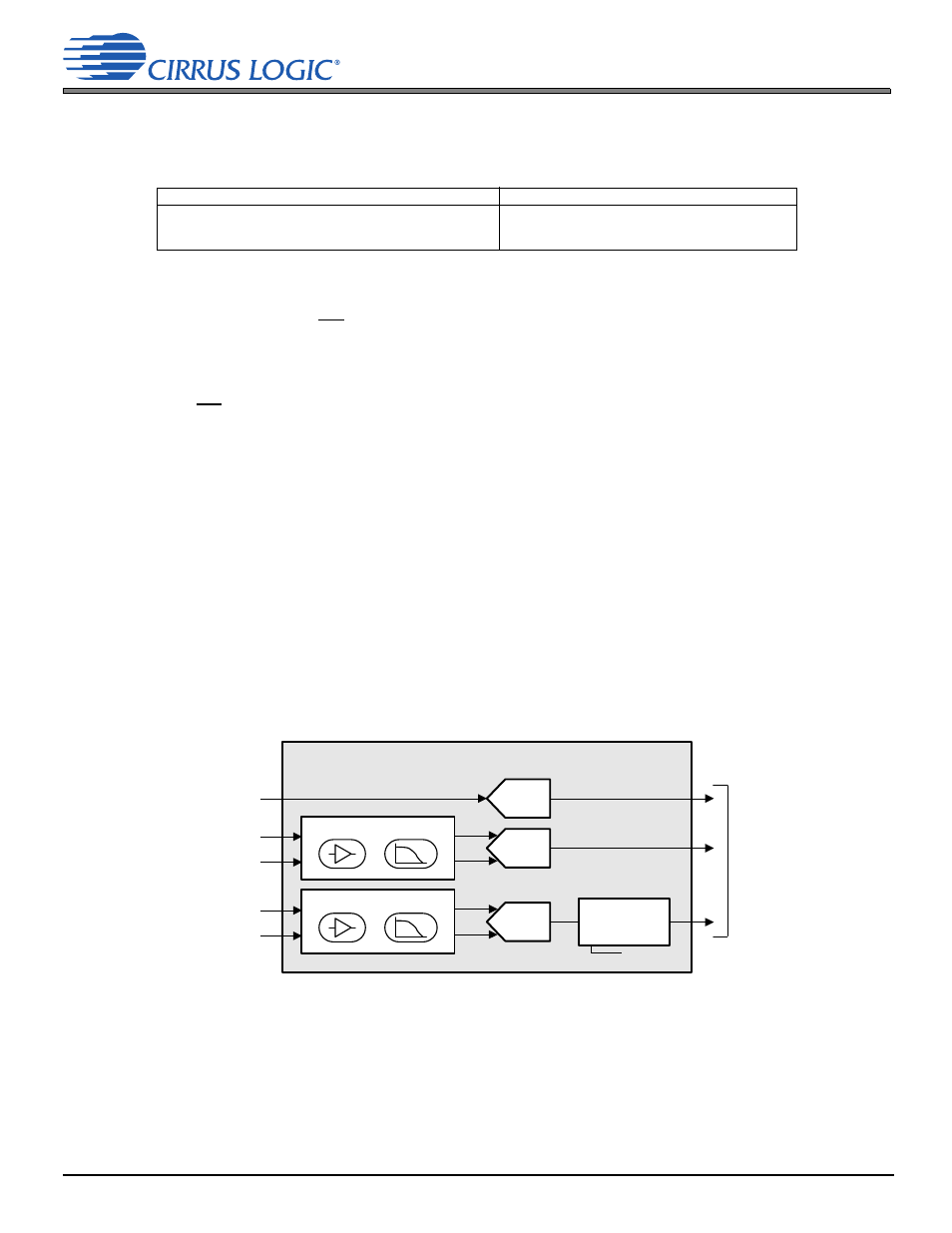
4.8 Signal Monitoring
Signal-monitoring ADCs, shown in
, give upstream system processors access to important signals entering and
exiting the device. The three monitoring signals are as follows:
• VPMON: Monitors the voltage on the VP pin, which is most commonly the battery for the system.
• VMON: Monitors the output voltage of the Class D amplifier.
• IMON: Monitors the current that flows into the load being driven by the Class D amplifier.
An integrated ADC digitizes these analog signals, at which point, the audio/data serial port (ADSP) can send them to the
system processor.
Figure 4-5. Signal Monitoring Block Diagram (PDN_xMON = 0)
4.8.1
Power-Up and Power-Down Bits (PDN_xMON)
The three ADCs can be powered down independently via their respective PDN_xMON bit in the control port, see
. To power down an ADC and its associated support circuitry, its PDN_xMON bit must be set; clearing PDN_
xMON powers up the corresponding circuitry.
Note:
For proper operation, MCLK must be at the correct frequency (
= 0; see
) and the device must
be powered (
= 0; see
).
Table 4-3. Die Temperature Monitoring Configuration
Error
Cross-Reference to Register Field Description
Overtemperature error/Overtemperature error mask
Overtemperature warning/Overtemperature warning mask
Overtemperature error release
Signal Monitoring
VSENSE+
Multibit
ADC
VSENSE–
ISENSE+
ISENSE–
Multibit
ADC
To Audio/
Data Serial
port
VP (3.0–5.25 V)
Multibit
ADC
Range Scaling
–30 to +36 dB
6-dB steps
VMON ADC Front End
LP
IMON ADC Front End
LP
(PDN_xMON = 0)