4 monitoring voltage on the vp pin—vpmon, 5 data transmission out of the cs35l32, 6 error conditions – Cirrus Logic CS35L32 User Manual
Page 21: 9 led driver, Section 4.8.4, Section 4.9, Led driver, Cs35l32
DS963F4
21
CS35L32
4.9 LED Driver
4.8.4
Monitoring Voltage on the VP Pin—VPMON
Monitoring of the voltage present on the VP pin is integrated internally to the CS35L32. The operating specifications for
this ADC path are given in
. To determine the voltage present on VP, the following equation must be used:
D
OUT
is the digital output word (see
) in signed decimal format (–128 to +127), and VA is the voltage on the
VA pin. If VA = 1.8 V, VPMON can report values from 2.8 V (D
OUT
= –77 decimal) to 5.52 V (D
OUT
= 0 decimal).
4.8.5
Data Transmission out of the CS35L32
The ADSP, described in
, can transmit all signals monitored in the CS35L32 to the system processor. The
data is presented on these outputs simultaneously.
4.8.6
Error Conditions
The CS35L32 monitors each monitoring ADC for overflow conditions.
lists signal monitoring error conditions and
provides links to their associated register field descriptions.
If an overflow occurs, the appropriate xMON_OVFL bit is set, and, if the respective mask bit is cleared, an interrupt occurs.
Exiting the error occurs when the signal is no longer overflowing. No release bit needs to be toggled.
• Overflow for VPMON and VMON signals. Due to the analog prescaling applied to the analog input signals, which
are sampled to make the VPMON and VMON signals, overflow conditions are unlikely on these ADCs. This is
because the operating specifications for maximum and minimum voltage constrain the voltage on these pins to a
level far below that required to make the ADC overflow.
For VPMON, because a spurious overflow error can occur when the block is taken out of power down, it is advised
to read the error status registers after PDN_xMON has been cleared to clear the spurious error status bit.
• Overflow for the IMON signal. As
(see
) control allows the
greatest possible sample resolution over a wide range of output currents and sense resistors. If IMON_SCALE is
set too low for either the output current being monitored or the sense resistor being used, overflow of this ADC can
occur. When this error occurs, increasing the IMON_SCALE value can prevent the sampled signal from overflowing.
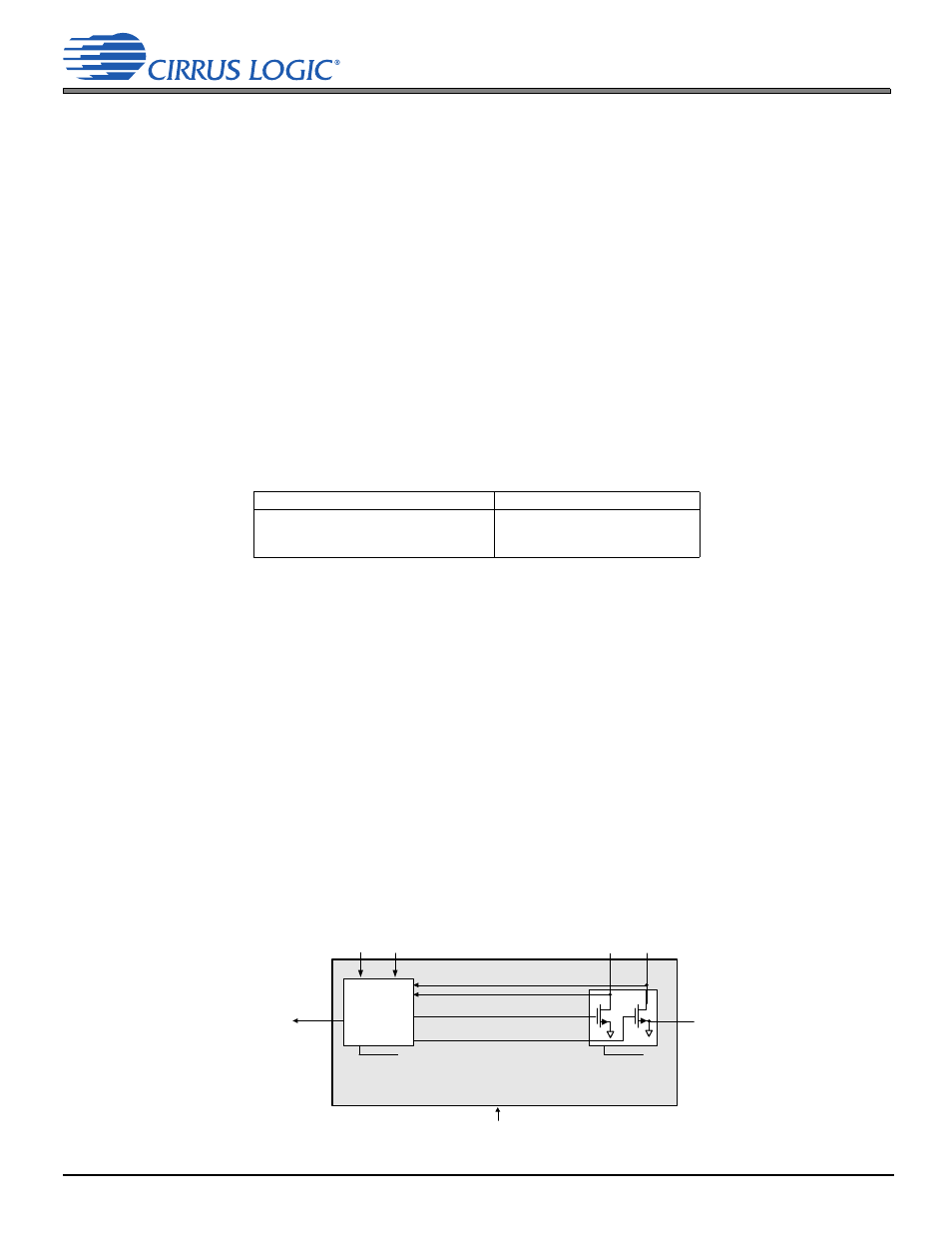
4.9 LED Driver
The CS35L32 includes a high-current flash LED driver (see
), featuring two channels, FLOUT1 and FLOUT2, and
a boost converter and current regulator designed to power LEDs with up to 0.75 A per channel. Both channels can be
combined to drive an LED with 1.5 A by tying FLOUT1 and FLOUT2 together.
Figure 4-6. LED Driver Block Diagram
Table 4-4. Signal Monitoring Error Status Conditions
Error
Cross-Reference to Description
xMON overflow. Indicates the overrange
status in the VMON, IMON, or VPMON
ADC signal paths.
VMON_OVFL p. 42
IMON_OVFL p. 42
VPMON_OVFL p. 42
VP
DOUT 128
+
255
--------------------------------------- 5
1
1.8
--------
+
VA
=
Flash LED Current Drivers
Control,
Sensing,
and Fault
Protection
FLOUT1
FLOUT2/AD0
FLEN FLINH
I
2
C Control Port
Current Mode
Boost Controller
GNDPLED