12 signaling format, 1 transmitting data, Cs35l32 – Cirrus Logic CS35L32 User Manual
Page 26
26
DS963F4
CS35L32
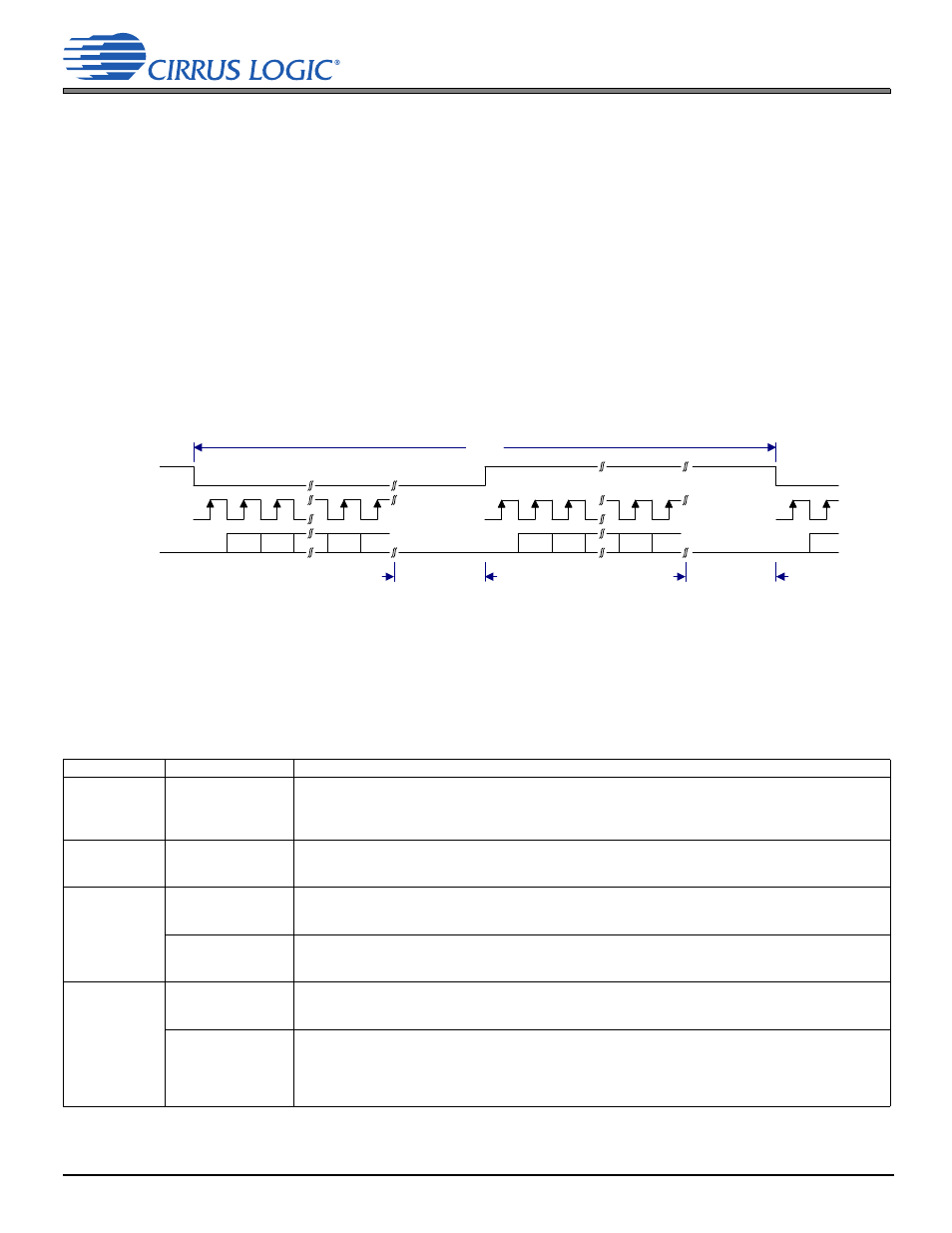
4.12 Signaling Format
The CS35L32 transmits data that is from 24 to 32 bits deep per channel sample. If fewer than 24 serial clocks are present
per channel frame (half LR clock period), it outputs as many bits as there are clocks. If there are more than 24 serial clocks
per channel frame, it outputs the bits shown in the extended section for the additional clock cycles after the 24th bit. Any
bit beyond the 24th, if marked as reserved, is zero. The receiving device is expected to load the data in MSB-to-LSB order
until its word depth is reached, at which point it should discard any remaining LSBs from the interface.
4.12 Signaling Format
The CS35L32 supports the I²S format on its serial port:
• Up to 32 bits/channel of composite data can be sent, as shown in
. Additional bits are packed
in the extended section, beyond the 24th bit, and are accessed if a 32-clock frame is used.
• LRCK identifies the transmission start of each channel.
• Data is clocked out of the SDOUT output using the falling edge of SCLK.
• Bit order is MSB to LSB.
Signaling for I²S format is shown in
.
Figure 4-10. I²S Format
4.12.1 Transmitting Data
The CS35L32 includes real-time monitoring of several signals internal and external to the device via integrated ADCs, as
well as a number of status bits. The monitoring data exists as three signals—VPMON, VMON, and IMON—which are
described in
and
, which also describes status bits.
Table 4-8. SDOUT Monitor Data Description
Function
Data Descriptor
Description
.
AMP_SHORT
(amplifier short)
Indicates that either of the outputs (OUT+ and/or OUT–) of the amplifier is driving a short circuit
0 (Default) Not shorted
1 Shorted. When this condition exists, the device enters Speaker-Safe Mode.
See
and
.
Undervoltage
Lockout (UVLO)
Section 4.5
.
UVLO
(UVLO event)
0 (Default) No undervoltage lockout
1 UVLO detected at VP. IC shut down.
See
.
.
BOOST_CURLIM
(boost converter in
current limit)
0 (Default) Boost converter is not in current limit
1 Boost converter is in current limit
See
.
BOOST_OVERROR
(boost converter
overvoltage error)
0 (Default) No overvoltage detected
1 Overvoltage detected
See
.
.
OTW
(overtemperature
warning)
Indicates that device junction temperature exceeded the set limit in
0 (Default) Junction temperature is below the set overtemperature warning threshold
1 Junction temperature is above set overtemperature warning threshold
OTE
(overtemperature
error)
Indicates whether the device junction temperature exceeded the damage limit
0 (Default) Junction temperature is below damage limit
1 Junction Temperature is above damage limit. When this condition exists, the device enters
Speaker-Safe Mode.
See
and
.
LRCK
SCLK
SDOUT
MSB
MSB-1
LSB +1
LSB
1/Fs
ext
MSB
MSB-1
LSB +1
LSB
MSB
SCLK may
stop or continue
t
extraA =
None to some time
SCLK may
stop or continue
t
extraB =
None to some time
Left (A) Channel
Right (B) Channel