4 functional description, 1 power supplies, 2 interrupts – Cirrus Logic CS35L32 User Manual
Page 15: Section 4.1, Cs35l32
DS963F4
15
CS35L32
4 Functional Description
4 Functional Description
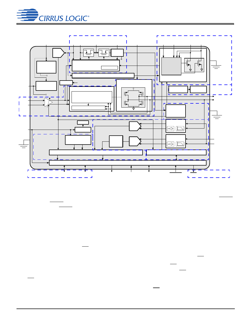
Figure 4-1. CS35L32 Block Diagram
4.1 Power Supplies
The VA and VP supplies are required for proper operation of the CS35L32. Before either supply is powered down, RESET
must be asserted. RESET must be held in the asserted state until all supplies are up and within the recommended range.
Timing requirement for RESET during supply power up and power down is described in
. The VBST supply is
generated internally (as described in
) and connected to the high-power output stage of the Class D amplifier
through two balls: VBST and SPKRSUPPLY. By so doing, the speaker amplifier benefits from the proximity of the external
decoupling capacitor that is connected to the boosted supply.
4.2 Interrupts
Events that require special attention, such as when a threshold is exceeded or an error occurs, are reported through the
assertion of the interrupt output pin, INT. These events are captured within the interrupt status registers. Events can be
individually masked by setting corresponding bits in the interrupt mask registers.
lists interrupt status and mask
registers. The configuration of mask bits determines which events cause the immediate assertion of INT:
• When an unmasked interrupt status event is detected, the status bit is set and INT is asserted.
• When a masked interrupt status event is detected, the interrupt status bit is set, but INT is not affected.
Once INT is asserted, it remains asserted until all unmasked status bits that are set have been read. Interrupt status bits
are sticky and read-to-clear: Once set, they remain set until the register is read and the associated interrupt condition is
not present. If a condition is still present and the status bit is read, although INT is deasserted, the status bit remains set.
Class D Power Stage
SPKR SUPPLY
VP
GNDPLED
Current Mode Synchronous
Boost Controller
VCOM
Range
Scaling
Class D Front End
Short Circuit Protection
∆Σ Class D Modulator
V
REF
Generation
Bandgap
Voltage
Generation
FILT+
VREF
ISENSE+
ISENSE–/
VSENSE+
GNDA
SCLK
LRCK
Soft Ramp
Level Shifters
I²C Control Port
SDA
SCL
SCLK
LRCK
SDOUT
MCLK
IN–
–
+
9,12,15, or
18 dB + Mute
IN+
Flash LED Current Driver
Control,
Sensing,
and Fault
Protection
FLOUT1 FLOUT2/AD0
FLEN FLINH
SPKOUT+
SPKOUT–/
VSENSE–
I
2
C Class G Override
Watchdog
Error
GNDP
VSENSE–
VSENSE+
ISENSE–
ISENSE+
SPKR
SUPPLY
ADC
Serial Audio/Data Port
Serial Port
Clock Generation
VA
RESET
INT
VMON ADC
Front End
LP
IMON ADC
Front End
LP
Low Battery Management
Class G
VBST
Current
Sense
IREF+
SW
Power
Budgeting
Temperature
Sensor
Overtemp
Protection
ADC
ADC
See
“
See
“
“
.”
See
,
.”
See
.
.”
See
.
See
.
See
,