18 interrupt mask 3, 19 interrupt status 1 (audio), Interrupt status 1 (audio) – Cirrus Logic CS35L32 User Manual
Page 41: Section 7.19, Interrupt mask 3, Section 7.18, M_lowbat, P. 41, Amp_short p. 41, Ote p. 41
DS963F4
41
CS35L32
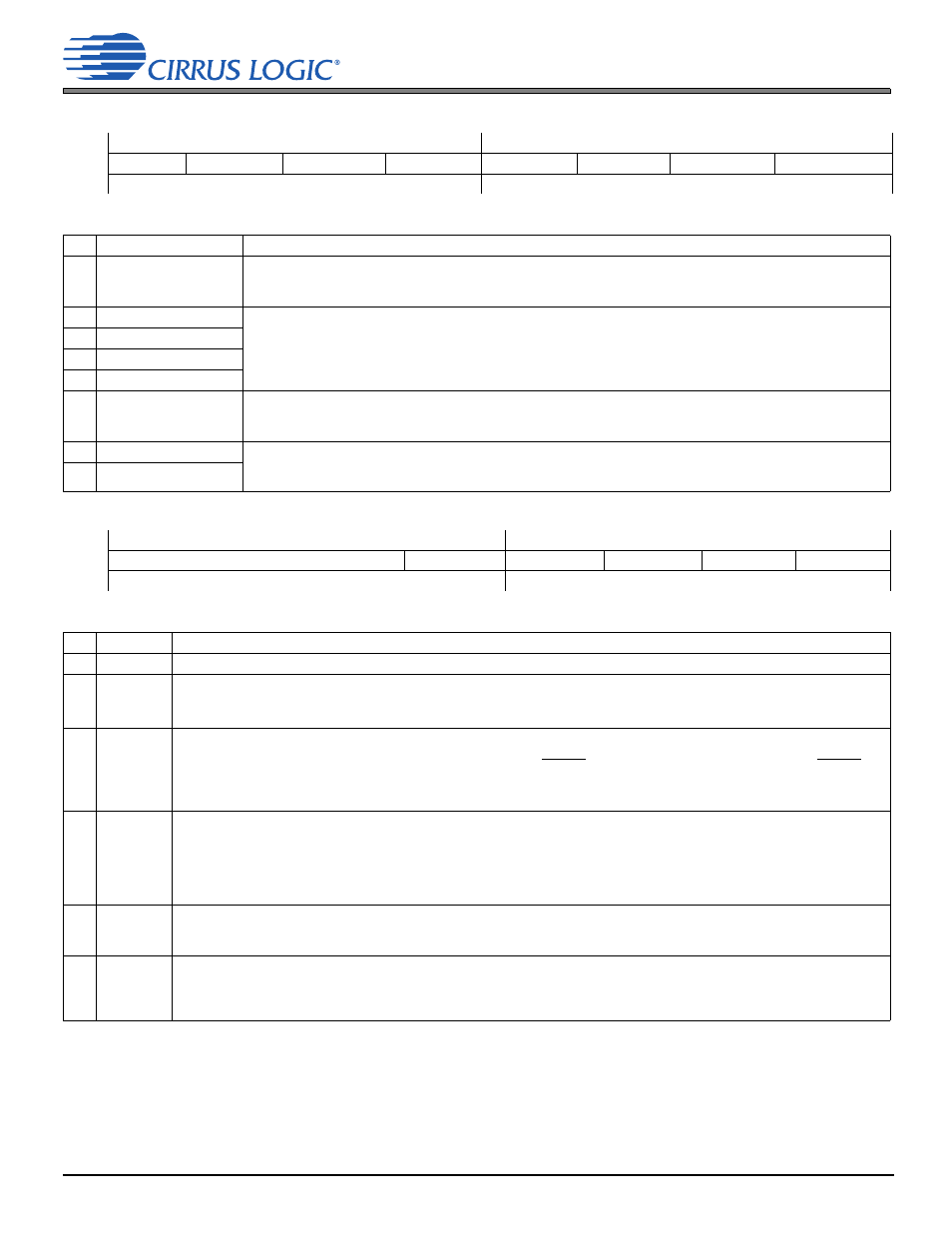
7.18 Interrupt Mask 3
7.18 Interrupt Mask 3
Address 0x14
R/W
7
6
5
4
3
2
1
0
M_UVLO
M_LED2_OPEN M_LED2_SHORT M_LED1_OPEN M_LED1_SHORT
M_LOWBAT M_BOOST_CURLIM M_BOOST_OVERROR
Default
1
1
1
1
1
1
1
1
Interrupt mask register bits serve as a mask for the interrupt sources in the interrupt status registers. Interrupts are described in
.
Registers at addresses 0x14–0x17 must not be part of a control-port autoincremented read and must be read individually. See
.
Bits
Name
Description
7
M_UVLO
UVLO mask
0 Unmasked
1 (Default) Masked
6
M_LED2_OPEN
LED 2/1 open and shorted masks
0 Unmasked
1 (Default) Masked
5
M_LED2_SHORT
4
M_LED1_OPEN
3
M_LED1_SHORT
2
M_LOWBAT
Low battery mask
0 Unmasked
1 (Default) Masked
1
M_BOOST_CURLIM
Boost converter masks
0 Unmasked
1 (Default) Masked
0
M_BOOST_OVERROR
7.19 Interrupt Status 1 (Audio)
Address 0x15
R/O
7
6
5
4
3
2
1
0
—
ADSPCLK_ERR
MCLK_ERR
AMP_SHORT
OTW
OTE
Default
x
x
x
x
x
x
x
x
Interrupt mask register bits serve as a mask for the interrupt sources in the interrupt status registers. Interrupts are described in
.
Registers at addresses 0x14–0x17 must not be part of a control-port autoincremented read and must be read individually. See
Bits
Name
Description
7:5
—
Reserved
4
ADSPCLK_
ERR
ADSP clock error. Indicates that the ADSP has lost synchronization. See
and
for details.
0 (Default) MCLK
INT
-to-LRCK ratio is valid. Valid if f
LRCK
= f
MCLK(INT)
/RATIO
1 MCLK
INT
-to-LRCK ratio is invalid. Set as the ADSP resynchronizes on initial power up and application of clocks.
3
MCLK_
ERR
Master clock error. Indicates the MCLK watchdog status.
0 (Default) MCLK is above ~1.25 MHz.
1 MCLK is below ~1.25 MHz, so the device should be reset (RESET = HIGH
LOW), released from reset (RESET =
LOW
HIGH) when a valid MCLK is reapplied, and restarted. If this condition exists, the Class D amplifier
immediately stops switching and the outputs are internally clamped to ground
.
See
.
2
AMP_
SHORT
Amplifier short. Indicates that either of the amplifier outputs (OUT±) is driving a short circuit.
0 (Default) Not shorted
1 Shorted. The device enters Speaker-Safe Mode (see
). Normal behavior may resume when the short
condition ceases and AMP_SHORT_RLS is sequenced, as described in
.
Note: The circuit feeding this bit requires the amplifier to be fully powered and not in shut-down mode; if it is powered down
(PDN_AMP = 1) or in Speaker-Safe Mode, the detector indicates no short condition, even if speaker outputs are shorted.
1
OTW
Overtemperature warning. Indicates that device junction temperature exceeded the set limit, as described in
.
0 (Default) Below set overtemperature warning threshold
1 Above set overtemperature warning threshold
0
OTE
Overtemperature error. Indicates whether the device junction temperature exceeded the damage limit.
0 (Default) Below damage limit
1 Above damage limit. The device enters Speaker-Safe Mode (see
). Normal behavior may resume when
the OTE event ends and OTE_RLS is sequenced, as described in