2 connecting the rs-485 control interface, Connecting the rs-485 control interface, Figure 15: rs-485 connector pinout – Kramer Electronics VS-1616A User Manual
Page 26: Figure 14, Set dip 7 on (disabling null-modem adapter use
KRAMER: SIMPLE CREATIVE TECHNOLOGY
Installing the Balanced Stereo Audio Matrix Switcher
22
Female 25-pin D-sub
PIN 20 connected to PIN 6
Connect PINS 4, 5 and 8 together
Figure 14: Connecting a PC (with a 25-pin connector) without a Null-modem Adapter
2. Set DIP 7 ON (disabling Null-modem adapter use
6.7.2
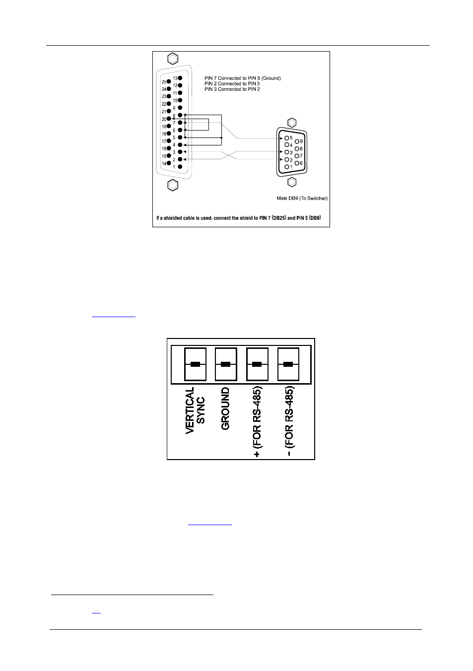
Connecting the RS-485 Control Interface
) on the VS-1616A
unit.
defines the RS-485 connector PINOUT for external RS-485
control. The RS-485 connector is also used (if required) for vertical sync:
Figure 15: RS-485 Connector PINOUT
To connect an RS-485 connector on one VS-1616A unit to an RS-485
connector on one or more other switchers (from the series of 16x16
matrix switchers), as
1. Connect the “+” PIN on the first VS-1616A unit to the “+” PIN on the
second VS-1616A unit or other unit
1 See section