2 setting the machine address, 3 understanding the system mode, Setting the machine address – Kramer Electronics VS-1616A User Manual
Page 21: Understanding the system mode, Table 5: machine # dip-switch settings, Table 5, A multi-channel audio switcher application, An expanded matrix switcher application, 17 table 5: machine # dip-switch settings
Installing the Balanced Stereo Audio Matrix Switcher
17
17
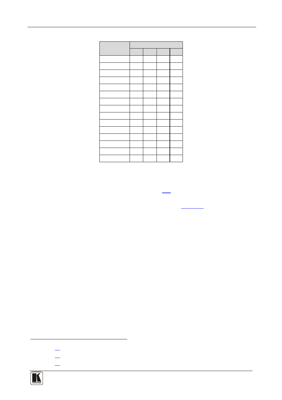
Table 5: Machine # DIP-Switch Settings
MACHINE #
DIP-SWITCH
1
2
3
4
1
ON
OFF OFF OFF
2
OFF ON
OFF OFF
3
ON
ON
OFF OFF
4
OFF OFF ON
OFF
5
ON
OFF ON
OFF
6
OFF ON
ON
OFF
7
ON
ON
ON
OFF
8
OFF OFF OFF ON
9
ON
OFF OFF ON
10
OFF ON
OFF ON
11
ON
ON
OFF ON
12
OFF OFF ON
ON
13
ON
OFF ON
ON
14
OFF ON
ON
ON
15
ON
ON
ON
ON
6.6.2
Setting the MACHINE ADDRESS #
The MACHINE ADDRESS # is determined via the MACHINE
ADDRESS Menu command, as section
ADDRESS # defines which inputs and outputs are configured to that
particular unit when expanding, as the chart in
A valid MACHINE ADDRESS # is from 1 to 36.
6.6.3
Understanding the SYSTEM Mode
DIP 5 defines whether the VS-1616A unit communicates with other
switchers via a common control line.
You can set DIP 5 OFF to disable the Follow-SYSTEM mode in the
following applications:
• Stand alone switcher applications
• A multi-channel audio switcher application
• An expanded matrix switcher application
You must set DIP 5 ON to enable the Follow-SYSTEM mode in an
interconnected varied-format switcher application
1 See section
and to allow control
from a PC via RS-232 or RS-485 using the K-Router application.
2 See section
3 See section