Goulds Pumps 3296 EZMAG - IOM User Manual
Page 92
Other Relevant Documentation or Manuals
• Broken or damaged coupling
• Jammed impeller
• Bad bearings
• Rapid cycling
The power draw at each of these conditions can be simulated in a plant test or estimated
through calculations or interpolations from the pump performance curve. By defining these
dangerous power fluctuations, appropriate calibration of the power-monitoring unit prevents
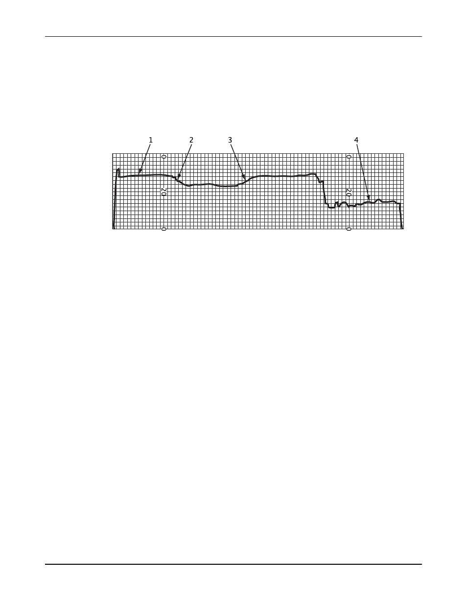
avoidable pump failures. This figure shows a typical power evaluation recorded from a common
centrifugal pump electric motor.
1. The pump is in operation.
2. The valve is closing.
3. The valve is opening.
4. There is no fluid being pumped.
Figure 16: Typical power evaluation
Contact your ITT representative for assistance and power analysis for your specific system. For
further details and evaluation of power monitoring units, a comprehensive power monitor user
guide is available from ITT.
Calibration tips
Use these tips to assist you when you select and calibrate power monitors:
• Read your power monitor installation instructions and wiring diagram before you attempt to
calibrate the unit.
• Understand the recommended operating envelope of your pump provided by ITT.
• Understand the requirements and limitations of your system.
• Understand the full range of your operating duty, including power requirements at the rated
minimum and maximum flow conditions.
• Identify potential failures that would be characteristic of your specific process and pump
type.
• Understand the power scope and torque scope of the selected electric motor.
• When feasible, further define your operating range to run as close to best efficiency point
(BEP) as practical.
• Select either a single trip unit or dual trip unit as practical for your specific system. A dual
trip unit is recommended for the 3296 EZMAG. Always use a low setting in order to protect
against dry run. A high setting detects if an upset condition has occurred. This results in
bearing damage.
• Set a low-power trip point at the required power draw when operation is at the
recommended minimum flow of the manufacturer or higher, but less that the normal
operating point.
• Set a high-power trip point at the required power draw when operation is at the
recommended maximum flow of the manufacturer or lower, or at the flow rate that will
prevent cavitation.
90
Model 3296 EZMAG Installation, Operation, and Maintenance Manual