Permitted indicator values for alignment checks, Cold settings for parallel vertical alignment, Alignment measurement guidelines – Goulds Pumps 3296 EZMAG - IOM User Manual
Page 24: Attach the dial indicators for alignment
Installation
Permitted indicator values for alignment checks
NOTICE:
The specified permitted reading values are valid only at operating temperature. For cold
settings, other values are permitted. You must use the correct tolerances. Failure to do so can
result in misalignment and reduced pump reliability.
When dial indicators are used to check the final alignment, the pump and drive unit are
correctly aligned when these conditions are true:
• The total indicator runout is a maximum of 0.002 in. (0.05 mm) at operating temperature.
• The tolerance of the indicator is 0.0005 in./in. (0.0127 mm/mm) of indicator separation at
operating temperature.
Cold settings for parallel vertical alignment
Introduction
This section shows the recommended preliminary (cold) settings for electric motor-driven
pumps based on different temperatures of pumped fluid. Consult driver manufacturers for
recommended cold settings for other types of drivers such as steam turbines and engines.
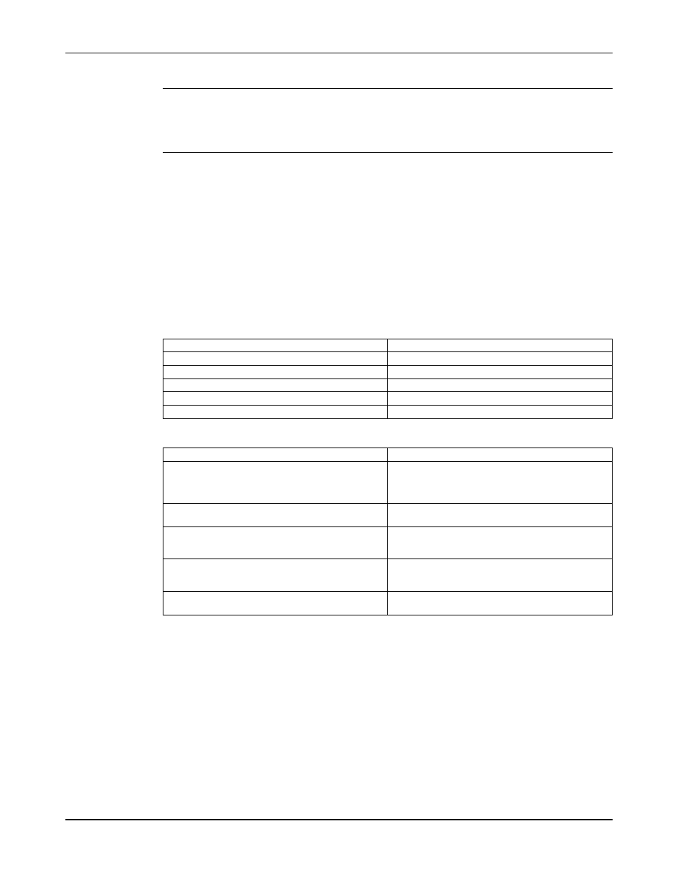
Recommended settings
Pumped fluid temperature
Recommended setting for driver shaft
50°F (10°C)
0.002 in. (0.05 mm), low
150°F (65°C)
0.001 in. (0.03 mm), high
250°F (120°C)
0.005 in. (0.12 mm), high
350°F (175°C)
0.009 in. (0.23 mm), high
450°F (218°C)
0.013 in. (0.33 mm), high
Alignment measurement guidelines
Guideline
Explanation
Rotate the pump coupling half and the driver
This prevents incorrect measurement.
coupling half together so that the indicator rods
have contact with the same points on the driver
coupling half.
Move or shim only the driver in order to make
This prevents strain on the piping installations.
adjustments.
Make sure that the hold-down bolts for the driver
This keeps the driver stationary since movement
feet are tight when you take indicator measure-
causes incorrect measurement.
ments.
Make sure that the hold-down bolts for the driver
This makes it possible to move the driver when you
feet are loose before you make alignment correc-
make alignment corrections.
tions.
Check the alignment again after any mechanical
This corrects any misalignments that an adjustment
adjustments.
may have caused.
Attach the dial indicators for alignment
You must have two dial indicators in order to complete this procedure.
1. Attach two dial indicators on the pump coupling half (X):
a) Attach one indicator (P) so that the indicator rod comes into contact with the perimeter
of the driver coupling half (Y).
This indicator is used to measure parallel misalignment.
22
Model 3296 EZMAG Installation, Operation, and Maintenance Manual