Goulds Pumps 3296 EZMAG - IOM User Manual
Page 27
Installation
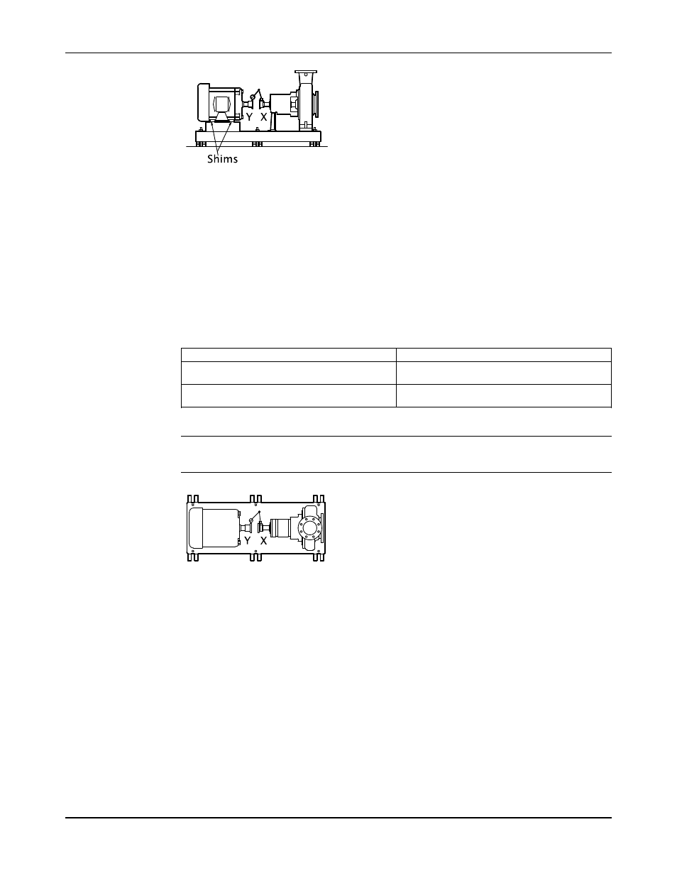
Figure 7: Side view of an incorrect vertical alignment
4. Repeat the previous steps until the permitted reading value is achieved.
Perform parallel alignment for a horizontal correction
Before you start this procedure, make sure that the dial indicators are properly attached for
measurement.
A unit is in parallel alignment when the parallel indicator (P) does not vary by more than
0.002 in. (0.05 mm) as measured at four points 90° apart at the operating temperature.
1. Set the parallel alignment indicator (P) to zero on the left side of the driver coupling half (Y),
90° from the top-center position (9 o’clock).
2. Rotate the indicator through the top-center position to the right side, 180° from the start
position (3 o’clock).
3. Record the indicator reading.
When the reading value is...
Then...
Negative
The driver coupling half (Y) is to the left of the
pump coupling half (X).
Positive
The driver coupling half (Y) is to the right of the
pump coupling half (X).
4. Slide the driver carefully in the appropriate direction.
NOTICE:Make sure to slide the driver evenly. Failure to do so can negatively affect
horizontal angular correction.
Figure 8: Top view of an incorrect horizontal alignment
5. Repeat the previous steps until the permitted reading value is achieved.
Perform complete alignment for a vertical correction
Before you start this procedure, make sure that the dial indicators are properly attached for
measurement.
A unit is in complete alignment when both the angular indicator (A) and the parallel indicator (P)
do not vary by more than 0.002 in. (0.05 mm) as measured at four points 90° apart.
1. Set the angular and parallel dial indicators to zero at the top-center position (12 o’clock) of
the driver coupling half (Y).
2. Rotate the indicators to the bottom-center position (6 o’clock).
3. Record the indicator readings.
4. Make corrections according to the separate instructions for angular and parallel alignment
until you obtain the permitted reading values.
When the procedure is complete, both the angular and parallel alignment must meet the
permitted tolerances.
Model 3296 EZMAG Installation, Operation, and Maintenance Manual
25