Specifications – NOVUS Controller N120 User Manual
Page 9
NOVUS AUTOMATION
9/14
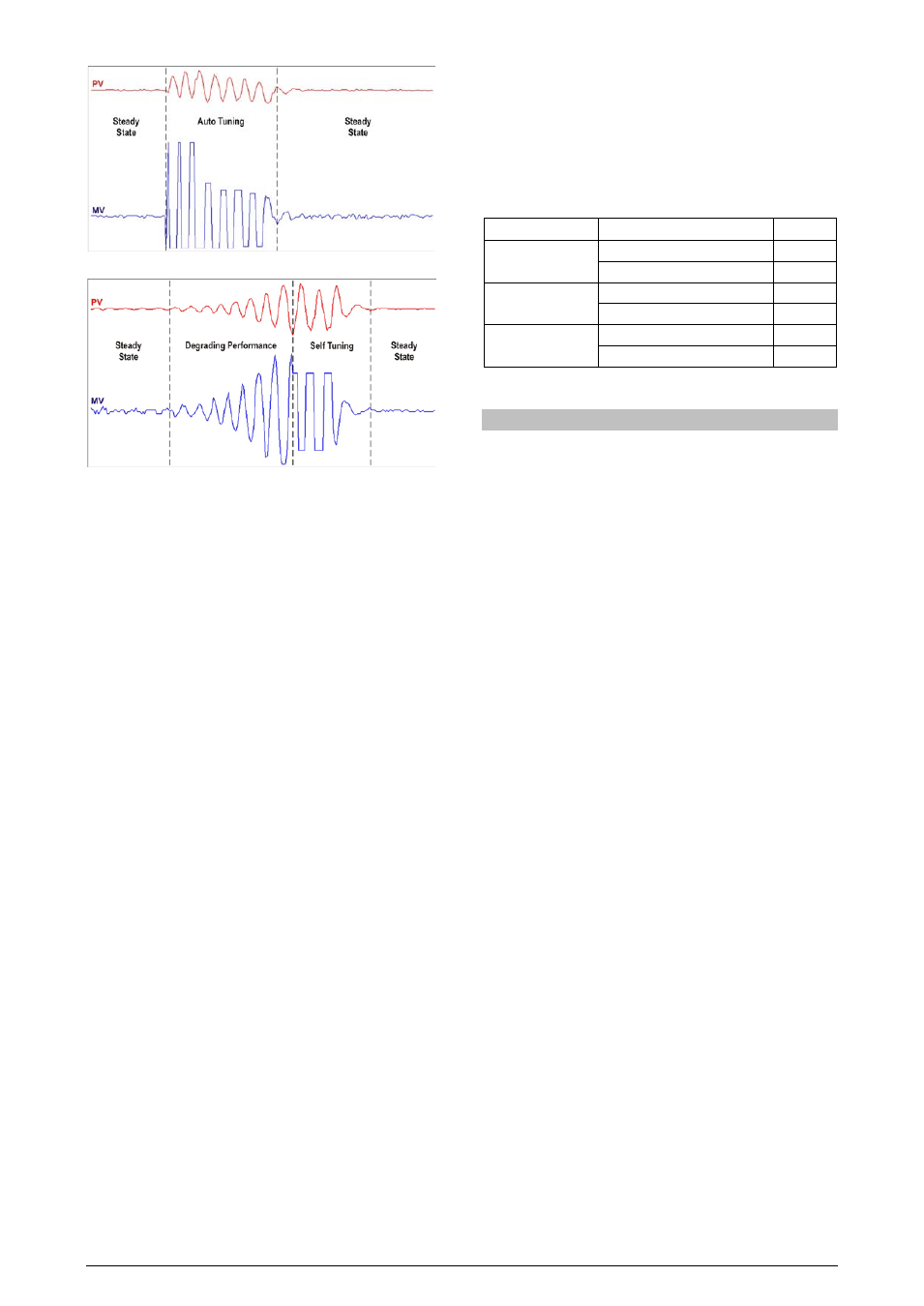
Fig. 7 – Example of auto tuning
Fig. 8 - Example of auto-adaptative tuning
The operator may select, through the ATUN parameter, the desired
tuning type among the following options:
• OFF: The controller does not carry through automatic tuning or
auto-adaptative tuning. The PID parameters will not be
automatically determined nor optimized by the controller.
• FAST: The controller will accomplish the process of automatic
tuning one single time, returning to the OFF mode after
finishing. The tuning in this mode is completed in less time, but
not as precise as in the FULL mode.
• FULL: The same as the FAST mode, but the tuning is more
precise and slower, resulting in better performance of the P.I.D.
control.
• SELF: The performance of the process is monitored and the
auto-adaptative tuning is automatically initiated by the
controller whenever the performance becomes poorer.
After the tuning process, the controller enters a learning phase
when it collects data relative to the process performance. This
phase, which is dependent of the response time of the process,
is indicated by a flashing TUNE indicator. Once this learning is
completed, the controller is able to decide whether of not a new
tuning is required to improve system response.
It is recommended not to turn the controller off neither change
the SP value during this phase.
• rSLF: Accomplishes the automatic tuning and returns into the
SELF mode. Typically used to force an immediate automatic
tuning of a controller that was operating in the SELF mode,
returning to this mode at the end.
• TGHT: Similar to the SELF mode, but in addition to the auto-
adaptative tuning it also executes the automatic tuning
whenever the controller is set in RUN=YES or when the
controller is turned on.
Whenever the parameter ATUN is altered by the operator into a value
different from OFF, an automatic tuning is immediately initiated by the
controller (if the controller is not in RUN=YES, the tuning will begin
when it passes into this condition). The accomplishment of this
automatic tuning is essential for the correct operation of the auto-
adaptative tuning.
The methods of automatic tuning and auto-adaptative tuning are
appropriate for most of the industrial processes. However, there may
be processes or even specific situations where the methods are not
capable to determine the controller's parameters in a satisfactory
way, resulting in undesired oscillations or even taking the process to
extreme conditions. The oscillations themselves imposed by the
tuning methods may be intolerable for certain processes. These
possible undesirable effects must be considered before beginning the
controller's use, and preventive measures must be adopted in order
to assure the integrity of the process and users.
The “TUNE” signaling device will stay on during the tuning process.
In the case of PWM or pulse output, the quality of tuning will also
depend on the cycle time adjusted previously by the user.
If the tuning does not result in a satisfactory control, refer to Table 7
for guidelines on how to correct the behavior of the process.
PARAMETER
VERIFIED PROBLEM
SOLUTION
Proportional Band
Slow answer
Decrease
Great oscillation
Increase
Rate of Integration
Slow answer
Increase
Great oscillation
Decrease
Derivative Time
Slow answer or instability
Decrease
Great oscillation
Increase
Table 07 - Guidance for manual adjustment of the PID parameters
SPECIFICATIONS
DIMENSIONS: .................................................................. 100 x 67 mm
.............................................................. Approximate Weight: 80 g
POWER SUPPLY:........... 100 to 240 Vac/dc (±10 %), 50/60 Hz, 5 VA
ENVIRONMENTAL CONDITIONS:
Operation Temperature: ............................................... 5 to 60 °C
Relative Humidity: ................................................ 80% max. 30 ºC
For temperatures above 30 ºC, reduce 3% for each ºC
INPUT ............. T/C, Pt100, voltage and current (according to Table 2)
Internal Resolution: .................................. 32767 levels (15 bits)
Resolution of Display: ..... 12000 levels (from - 1999 up to 9999)
Rate of input reading: ................................. up to 55 per second
Precision: .. Thermocouples J, K, T, E: 0.25% of the span ±1 ºC
.................... Thermocouples N, R, S, B: 0.25% of the span ±3 ºC
................................................................. Pt100: 0.2% of the span
............................................... 0-50 mV, 0-5 Vdc: 0.2% of the span
Input Impedance: 0-50 mV, Pt100 and Thermocouples: >10 MΩ
................................................................................. 0-5 V: >1 MΩ
Measurement of Pt100: ................ Three wire type, (α=0.00385)
with compensation for cable length, excitation current of
0.170 mA
All input and output types are factory-calibrated. Thermocouples
according to standard NBR 12771 / 99, RTD’s NBR 13773 / 97.
Heating Time: ..................................................................... 15 minutes
ENTRADA DIGITAL(DIG INP): .. Contato Seco ou NPN coletor aberto
OUT1: ..................................................... Pulso de tensão, 5 V / 20 mA
OUT2 (*): ..................................................... Relé SPST, 3 A / 250 Vca
OUT3: .......................................................... Relé SPST, 3 A / 250 Vca
(*) In models with adjustable outputs – PR, one relay SPDT-NO 10 A
/ 250 VAC is available at OUT2. These models will not be available
the OUT3.
USB INTERFACE: 2.0, CDC CLASS (virtual communications port),
MODBUS RTU protocol.
SUITABLE FOR TERMINAL CONNECTION TYPE FORK
CYCLE PWM PROGRAMMABLE FROM 0.5 TO 100 SECONDS;
STARTS UP OPERATION: after 3 seconds connected to the power
supply.