Scale level, I/o cycle (inputs and outputs), Calibration cycle – NOVUS Controller N120 User Manual
Page 7: Protection of configuration, Xya3 xya4, Flsh, Type, Fltr, Dp.po, Vnit
NOVUS AUTOMATION
7/14
xya3
xya4
at which it is turned off (in engineering units).
A1t1
A2t1
A3t1
A4t1
Alarm Time t1. Defines the temporization time t1, in
seconds, for the alarms. Defines the temporization time
t1, in seconds, for the alarms time functions.
The value 0 (zero) disables the function.
A1t2
A2t2
A3t2
A4t2
Alarm Time t2. Define intervalo de tempo t2 para a
temporização nos acionamentos dos alarmes. Em
segundos.
O valor 0 (zero) desabilita a função.
flsh
Flash. Allows visual signalization of an alarm occurrence
by flashing the indication of PV in the operation level.
The user chooses which alarms are to be associated
with this feature.
SCALE LEVEL
Type
Input Type. Selects the input signal type to be connected
to the process variable input. Refer to Table 2 for the
available options.
Necessarily the first parameter to be configured.
fltr
Digital Input Filter. Used to improve the stability of the
measured signal (PV). Adjustable between 0 and 20. In
0 (zero) it means filter turned off and 20 means
maximum filter. The higher the filter value, the slower is
the response of the measured value.
Dp.po
Decimal Point. Selects the decimal point position to be
viewed in both PV and SP.
vnIt
Unit. Temperature indication in ºC or ºF. Not shown for
linear inputs.
Parameter presented when used temperature sensors.
0ffs
Sensor Offset. Offset value to be added to the PV
reading to compensate sensor error.
Default value: zero.
Spll
Setpoint Low Limit. Defines the SP lower limit of.
For the linear analog input types available (0-20 mA, 4-20
mA, 0-50 mV and 0-5 V), defines the minimum PV
indication range, besides limiting the SP adjustment.
Defines lower limit for range retransmission PV and SP.
Spxl
Setpoint High Limit. Defines the upper limit for adjustment
of SP.
For the linear analog input types available (0-20 mA, 4-20
mA, 0-50 mV and 0-5 V), defines the maximum PV
indication range, besides limiting the SP adjustment.
Defines upper limit for range retransmission PV and SP.
1eov
Percentage output value that will be transfer to MV when
the SAFE output function is enabled. If 1eov = 0, the
SAFE output function is disabled and the outputs are
turned off in the occurrence of a sensor fail.
bavd
Digital communication Baud Rate selection, in kbps: 1.2,
2.4, 4.8, 9.6, 19.2, 38.4, 57.6 and 115.2
prty
Parity of the serial communication.
none
- Without parity
Euen
- Even parity
0dd
- Odd parity
Addr
Slave Address Selection. Identifies the controller in the
network. The possible address numbers are from 1 to
247.
I/O CYCLE (INPUTS AND OUTPUTS)
ovt1
I/O 1 Function: Selects the I/O function to be used at I/O
1 (relay 1).Refer to Table 3 for functions.
ovt2
I/O 2 Function: Selects the I/O function to be used at I/O
2 (relay 2).Refer to Table 3 for functions.
ovt3
I/O 3 Function: Selects the I/O function to be used at I/O
3 (relay 3).Refer to Table 3 for functions.
d.in1
Digital Input Function (DIGITAL INPUT). As Table 4.
CALIBRATION CYCLE
All of the input and output types are calibrated in the factory. If a
recalibration is required, this should be carried out by a experienced
personnel. If this cycle is accidentally accessed, pass through all the
parameters without pressing the or keys
pass
Input of the Access Password.
This parameter is presented before the protected cycles.
See item Protection of Configuration.
(alib
Allows instrument calibration.
Yes
- Perform calibration
NO
- Do not perform calibration
inL(
Input Low Calibration. See section MAINTENANCE /
Input Calibration.
Enter the value corresponding to the low scale signal
applied to the analog input.
ink(
Input High Calibration. See section MAINTENANCE /
Input Calibration.
Enter the value corresponding to the full scale signal
applied to the analog input.
rstr
Restores the factory calibration for all input, analog
output and remote SP, disregarding modifications carried
out by the user.
(j
Adjusts the of cold junction temperature value.
Pas.(
Allows defining a new access password, always different
from zero.
Prot
Sets up the Level of Protection. See Table 6.
Freq
Mains frequency. This parameter is important for proper
noise filtering.
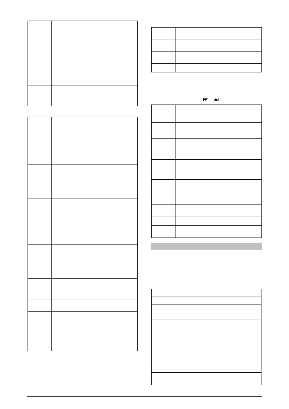
PROTECTION OF CONFIGURATION
The controller provides means for protecting the parameters
configurations, not allowing modifications to the parameters values,
avoiding tampering or improper manipulation.
The parameter Protection (PROt), in the Calibration level,
determines the protection strategy, limiting the access to particular
levels, as shown by the table below.
Protection level
Protected cycles
1
Only the Calibration level is protected.
2
Outputs and Calibration levels are protected.
3
Scale, Outputs and Calibration levels are protected.
4
Alarm, Scale, Outputs and Calibration levels are
protected.
5
R&S Program, Alarm, Scale, Outputs and Calibration
levels are protected.
6
Tunning, R&S Program, Alarm, Scale, Outputs and
Calibration levels are protected.
7
Operation (except SP), Tunning, R&S Program,
Alarm, Scale, Outputs and Calibration levels are
protected.
8
Operation, Tunning, R&S Program, Alarm, Scale,
Outputs and Calibration levels are protected.
Table 7 – Levels of Protection for the Configuration