Appendix 1 - software logchart-ii, Installing logchart-ii, Running logchart-ii – NOVUS Controller N120 User Manual
Page 11: Configuring the controller
NOVUS AUTOMATION
11/14
APPENDIX 1 - SOFTWARE LOGCHART-II
INSTALLING LOGCHART-II
LogChart II is the software provided with the logger to allow for
configuration and data offload. To install, run the LC_II_Setup.exe
file provided with the CD.
Note: Be sure your Windows date separator is configured as a slash:
dd/mm/yy or dd/mm/yyyy.
RUNNING LOGCHART-II
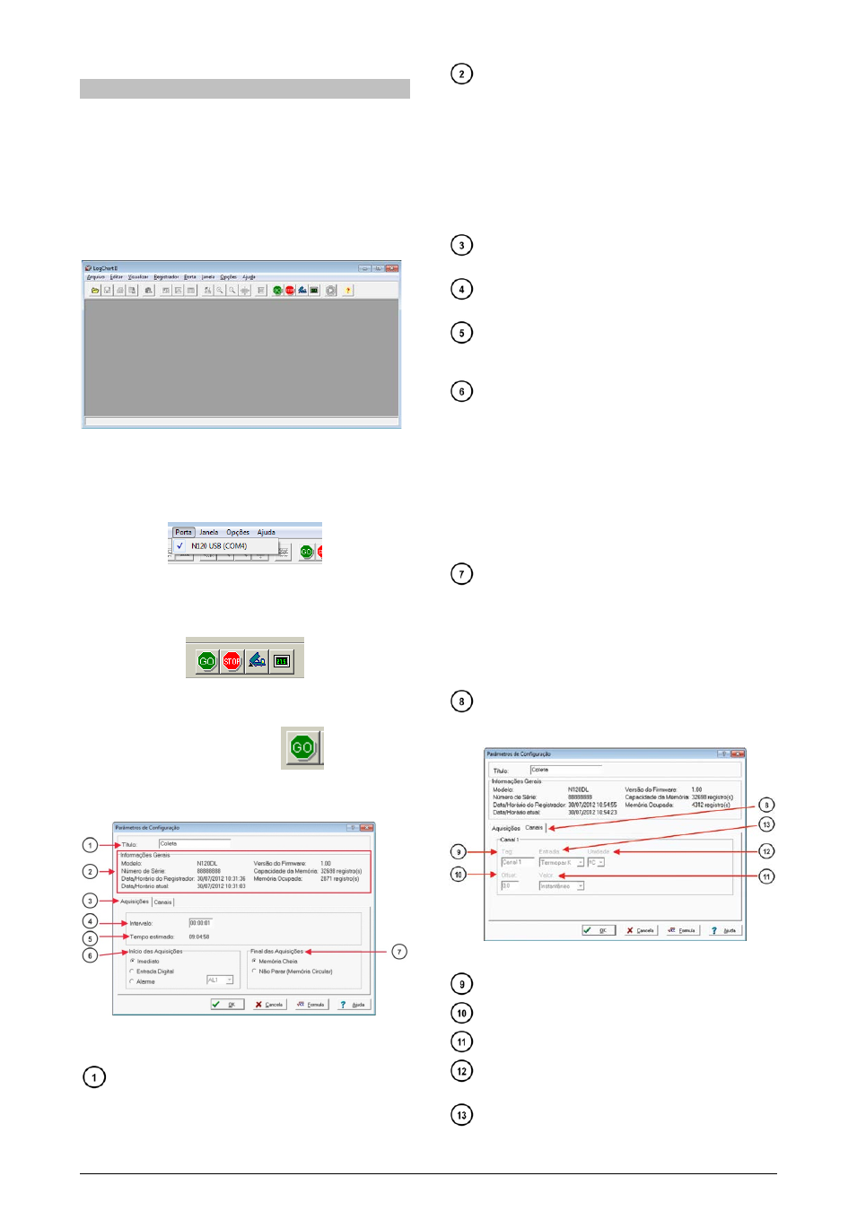
When you open LogChart-II the main window is displayed:
Fig. 1 – LogChart-II main window
Then indicate the serial port to be used by the communication
interface through the "Port" menu. This menu lists all available serial
port on your computer. You must select a port that shows the N120
equipment in their description.
Fig. 2 – Selection of USB serial port where the N120 controller is connected.
Once a valid serial port is selected, the icons for communication with the
controller will be activated.
Fig. 3 – Icons enabled when the communication port selected is a valid port
CONFIGURING THE CONTROLLER
To configure the controller press the button:
The Configuration Settings window is displayed. This LogChart-II
window allows the user to set the operating mode of the controller
and also provide general information about the device (Fig. 4).
Fig. 4 – Logger Set Up (Readings)
The configuration fields are:
Title: In this field, the user identifies the records giving it a
name (up to 16 characters).
General Information: Information field. There are presented
information regarding the controller, including: Model (N120), serial
number, date/time of the controller, current date/time of the PC,
firmware version (model controller), memory capacity and number of
acquisitions in memory.
In this field the time is constantly updated while the communication
between controller and computer is established.
Note: The clock of the controller may be with a little difference
compared to the current time of the computer. When the controller is
configured their clock is updated.
Acquisitions: Presents a series of parameters that define how
measurements will take place.
Interval: Defines the interval between readings: Minimum
interval is 1 (one) second.
Estimated time: In this parameter, the logger informs the user
how long it will take to occupy the full memory, in the conditions
set up during configuration.
Start of Readings: Readings can be started in one of five
different modes:
• Immediately: start as soon as programming is considered
to be ready, and is then sent (OK) to the logger.
• Digital Input: The acquisitions are started whenever the
digital input of the N120 is activated. Otherwise, the
acquisitions are interrupted
• Alarm: the acquisition starts whenever the condition
associated with the alarm 1 (AL1) controller is met.
Otherwise, stops the acquisition.
End of the acquisitions: The options for the ending of
acquisitions are:
• Memory Full: acquisitions are made up to the capacity of
the memory available.
No Stop (Circular Memory): acquisitions happen continuously,
overwriting the oldest registers as the number of acquisitions
exceeds the memory capacity.
Channels: Shows parameters referring to each channel
separately. Channel 1 is the Temperature channel, and Channel 2
the Relative Humidity channel.
Fig. 5 – Logger Set Up (Channels)
Tag: Defines a name for the temperature registers.
Offset: Makes possible to correct the value logged.
Valor: It defines how the value measured will be registered.
Unit: Defines the unit of the value measured: ºC or ºF for
channel 1 (temperature).
Entrada: The alarm limit value is shown with a dotted line with
the same color of the channel 1.